Category: 3D Printing

Well 3D printing of course

3D print Hangout, July 10, 2017

We had another fun 3D print hangout last night.

Two newcomers and two veterans came, plus a few more who popped in later.

Just a reminder that we always start with 3D print 101, which takes about 45 minutes. The unstructured hang-out starts afterward. If you’re an experienced 3D-print veteran, it’s perfectly okay to skip the training and show up later. Bring your latest stuff; we’d all love to see it!

I brought my new rope-making gadget-set. I used ball thrust-bearings throughout, since I figured there would be a lot of friction once the rope strands were under tension. It was a great exercise in mating 3D printed parts to fit stock hardware–getting dimensions and clearances right is always a challenge.


I’m really happy with the result. It works great and makes a fun demo since it takes three people to use it. Nothing like having volunteers turn a crank and watch something new emerge before their eyes!

The big news of the night was Melissa’s new 3d printer! It’s an older laser-cut plywood PrintrBot simple she found online. It has a few miles on it to say the least; frankly I was not too optimistic. The gantry sagged, and I’d never worked with a ‘string drive’ before.

Still, all the electronics checked out; and the hot-end reached and held temperature just fine, so I set her to work tightening up and replacing a few dodgy-looking zip-ties.

That done, we configured Slic3r; leveled the bed and gave it a shot: The calibration cube printed just fine!

Even if it hadn’t worked out, an older project printer like this can sometimes still be a good deal for the components alone. The stepper motors seem to live forever, as do the electronics, linear bearings, etc. If you want a fun project; keep your eyes peeled for deals!

Don’t let inexperience be a barrier: I learned everything I know about it by surfing online. And of course, you can come to us if you need help.

Important note: our next hangout will be on Tuesday the 25th. That’s a day later than originally scheduled.


3D Print Hangout, May 1, 2017

Whew! it’s been a while since my last 3D print hangout write-up!  We continue to hold this event every two weeks.  We had a good turnout this week; about a dozen guests.
Terry brought along his Monoprice Mini that he got a few months ago for about $150.00.  It has  a small build area, but works right out of the box and has a large online community.
Terry also found a neat cabinet that the printer fits in perfectly.  It was originally designed for network appliances.  He lined it with foam for additional noise cancelling.
Will brought his nascent Prusa rework Reprap machine in for a bit of show-and-tell and tuning.  We got it going, and did some brainstorming for improvements.  Parts for this machine were made right here at AMT on our own 3D printers and Laser cutter.  Yes, you can make your own 3D printer!  If you’re interested, let us know.  We can even supply some of the parts from our stash.
 
Terry and a number of other members have expressed interest in deploying Octoprint for our printers.  Click out the link if you want to learn more about it.  We had a look at it and debated the pros and cons during this meeting.  I’m not entirely convinced it’s worth the effort, but Octoprint fans really love it.  I’d like to organize a task-team to set up a trial-deployment.  If you’re interested in participating, contact me on Slack!
 
Just a reminder, we now officially start the meeting with a 3D print 101 training session which takes about 45 minutes or so.  You may come later if you want to skip that part. Non members are always welcome.  Come join us!

Cool new sample shelf!

At last week’s Thursday gathering, I put out a general cry for help.  We needed a better way to show off the various 3D print samples we’ve accumulated over the years.

Devon was there and rose to the challenge.

If you are looking for a project to hone your maker skills, just talk to your friendly neighborhood steward.  I’m sure we all have a list of projects like this that will benefit the space.

Thanks Devon!

New 3D printer at Ace Monster Toys!

Over the last year it has become evident that our fleet of 3D printers is showing its age. First I upgraded the Type-A printer with a new hot-end and LCD/SD card reader.  It’s much improved, but still not reliably producing the quality I was hoping for. Meanwhile the Replicator 2 had an alarming number of maintenance issues.  Among other things I had to completely replace the hot end, and add a ‘bypass’ circuit to get the extruder fan running reliably. I’ve managed to keep both printers working (they’re still in good order as I write this), but my confidence in their long-term prospects is not high. Rachel suggested I look into a replacement.

So, a few months back, I made a list of criteria and started searching in earnest. I’d originally thought about building a machine from scratch, but ultimately decided on the “Original Prusa i3 MK2.” It ticked off most of the boxes on my list, and has received rave-reviews. Ours has been assembled, tested, calibrated, and deployed for use for about a week now.

Why this one?

So, why did I choose this printer? …particularly when inexpensive printer kits can be had for less than $200.00 these days?

Well, the inexpensive machines sold on AliExpress and elsewhere are great deals for individuals who don’t mind doing a bit of fiddling around. I still recommend them if you’re on a budget, and am more than happy to help if you need it.

Personally, I’ve always wanted to understand how things work, and have always preferred to build something myself rather than buy it. When I first joined AMT, I figured I’d be surrounded by like-minded folks.  We are hackers, right?  Those $200.00 printers are for hackers.

But, much to my surprise, most folks I’ve assisted here at AMT have no desire whatsoever to understand the inner workings or finer points of our 3D printers.  They just want to use the machine, with as little training as possible.  So, reliability and ease-of-use turn out to be all-important.

The Original Prusa i3 MK2 is about the least-expensive 3D printer that fits the bill. It’s a substantial improvement over the older i3 design that most of the clones are based on. (I really think he should have given it a newer, more distinctive name.) It features:

  • Automatic bed leveling! This addresses the number-one issue that plagues even experienced users here at AMT.
  • A special edition of the open-source Slic3r program, preconfigured for all common filament types.
  • A PEI bed surface for good adhesion and surface quality; no need for blue tape!
  • A special heated bed with varying trace density for even heat (an i3 MK2 exclusive, as of this writing).
  • Great documentation and support.
  • A genuine RAMBO electronics board.  This is probably the best 8-bit option available and features fuses on high-draw circuits.
  • A genuine E3D hot-end; not a cheap knockoff.
  • A machined aluminum frame with a rugged finish (many clones are acrylic).
  • High quality stepper motors, precisely matched to their function.
  • Precision lead-screws on Z-axis, integral to the stepper motors (no wobbly coupling nut).
  • Printed parts of the highest quality.
  • Well-thought-out wiring paths; no dangling cables.
  • Firmware that includes self tests, auto calibration, …even corrects for out-of-square assembly!
  • The entire design remains open-source in case replacement parts must be 3d printed. I damaged a minor part during initial assembly and was able to simply print another.

Besides all that, Josef Prusa has probably done more for open-source 3D printing technology than anyone. He and his company deserve our business.

Training now required

I host training sessions all the time, but we’ve never actually required training to use our 3D printers. They’re not all that difficult to use, and there’s little risk of hurting yourself.

But, during my tenure here (about a year now) I have run into a number of users who really should have had proper training. In some cases they risked damaging the machines. So I suggested that we tighten this policy up at a meeting a few months ago and got enthusiastic support. Starting now, training is required.

While the i3 MK2 is certainly the easiest of our printers to use, there are a few important things to know. Training only takes about 30 minutes or so, and will henceforth be the first thing we do at every 3D Print Hangout (every other Monday night). I’ll also schedule a few extra “training only” sessions so that everyone has a chance to attend. Training is free and open to non-members as well. If you can’t attend a regularly-scheduled training, get in touch and I’ll work something out.

I hope you have fun with the new machine! We’re getting great results so far!

Oh, by the way: This printer does not feature dual-extrusion, but there is a spiffy ColorPrint utility that allows you to pause the job at a specific layer and change filament. It works great and is lots of fun to use!  I used it for the AMT logo in the photos.  (The checkerboard used a related but experimental technique… watch for a future post on the subject!)


Fusion 360 for Laser Cutting

Fusion 360 now has an experimental CAM feature to develop cutting paths for a laser cutter. I recently experimented with this feature, and thought I’d write up my findings.

These notes apply to our EXLAS 1280 laser cutter, which is driven by Lasercut 5.3 and accepts a DXF file as input. For non AMT readers, our laser cutter seems to be very similar to the RL-80-1290 sold by Rabbit Laser.

Background

It’s always been possible to use Fusion 360 to develop projects for our laser cutter. Taylor demonstrated it at one of his Fusion 360 workshops, and I’m sure more information can be found with a web search. Broadly, these are the steps:

  • Model your project as for any other media. Arrange bodies into ‘components’ as appropriate.
  • Copy each body to be laser cut to a new component called ‘cut layout’ or similar. Arrange the parts as desired, generally to minimize waste.

gatling-cutlayout

  • Create a new sketch and project all parts on the cut layout to the sketch plane.
  • Export this sketch as a DXF file.

The principal shortcoming of this approach is that the projected contours aren’t adjusted for the kerf of the laser cutter. Sometimes this doesn’t matter, but for parts that must precisely fit together (like the ubiquitous finger-jointed boxes) it can be an annoying problem.

We can adjust for kerf by doing some additional work right before exporting:

  • Edit the cut-layout sketch; Select each profile in turn and:
    • Apply the ‘offset’ tool, creating a new profile just outside the original. (For holes, offset inward.)
    • Select the original profile and delete it. (It’s probably smart to make a copy of your cut layout sketch first).
  • If you want ‘tabs’ to keep the pieces in the material sheet, they must be manually created: delete a small portion of the path at each desired location. I like to draw a small circle where I want the tab; use the ‘trim’ tool to delete the portion within the circle; then delete the circle.

Obviously, this is a major pain in the neck to maintain. If you didn’t get the kerf adjustment right the first time, or if your part dimensions or layout change, you must repeat these laborious steps. It’s an obvious application for a script or add-in, and I suspect something’s available but haven’t looked for it yet. Please post if you have an alternate technique!

Setting up for CAM

The new CAM support promises to address these shortcomings in a way that works more like the CAM workflow for milling or ‘CNC routing.’ To use it there are a few preliminary steps that must be done just once. These steps may become unnecessary when the feature passes out of the preview phase.

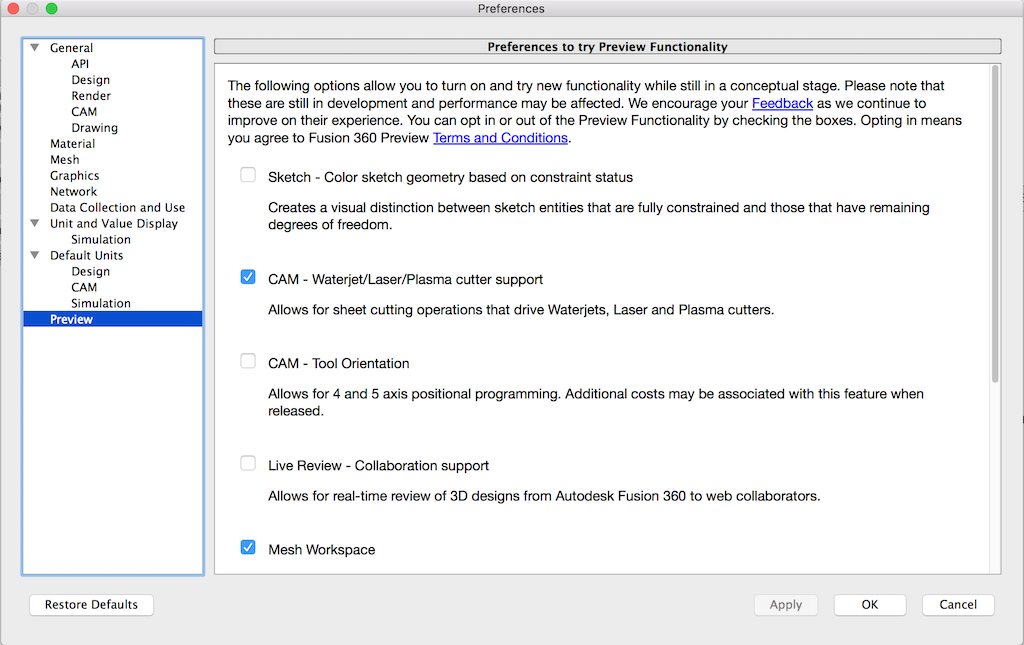
First turn the feature on: select ‘Preferences’ under your user name in the upper right corner. Then select ‘Preview’ and turn on ‘CAM – Water/Laser/Plasma cutter support.’

preview-prefs

Next, install the DXF ‘Post Process.’ This allows saving the tool path as a DXF file.

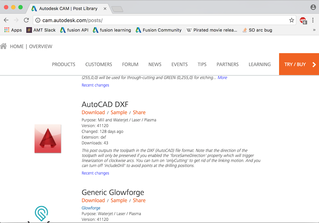
  • Browse here: http://cam.autodesk.com/posts/
  • In the ‘type’ dropdown, choose ‘Water / Laser / Plasma’
  • Then scroll down to ‘AutoCAD DXF’ and click ‘download’
  • Save the ‘dxf.cps’ file to your machine.

dxf-post

  • Install this post processor in your Fusion environment. On a Mac, you simply copy it to this directory:

/Users/<username>/Autodesk/Fusion 360 CAM/Posts

I’m sure there’s an equivalent on Windows. Please leave a comment if you figure out where it is.

Alternatively, you could also follow these steps, which put the post processor in the cloud so you can use it from multiple machines.

Creating the CAM tool path

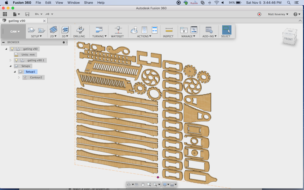
You’ll probably still want to create the ‘cut layout’ component as described above. The CAM support does nothing to help with this step. (…Another obvious application for a custom script or add-in.)

Then, with the cut layout component visible and other components hidden,

  • Enter the CAM workspace (the big gray menu on the left).
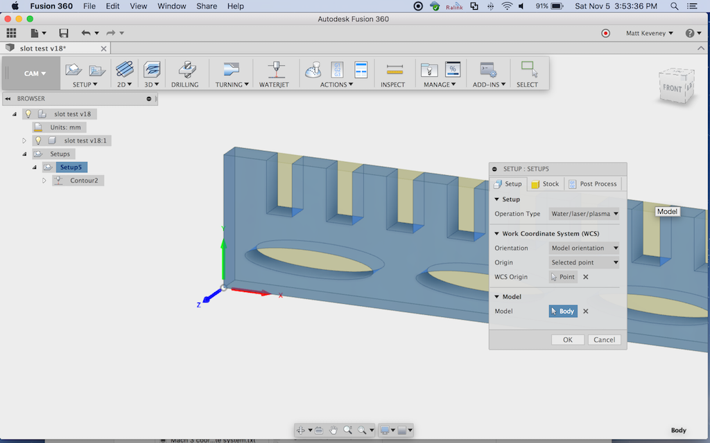
  • Select ‘New Setup’ and set values as follows:
    • On the ‘Setup/Operation Type’ tab, choose ‘Water/laser/plasma’
    • On the ‘Stock’ tab, I prefer to use ‘relative size box’ with all offsets set to zero. You could also enter your actual stock size if desired, but this merely serves as a visual reference; perhaps as a double-check of your part layout.
    • I like to set WCS to ‘model orientation’, ‘stock box point’, and then choose the lower-left corner of my stock box as illustrated here. This works the same as for milling operations.

stock-origin

  • Click OK to finish the setup, then click ‘WATERJET’ to create a new contour operation, and set values on each tab as follows:
  • ‘Tool’ tab:
    • Type: ‘Laser cutting.’
    • cutting mode: ‘Through – auto’ (I’m not sure what this does but it sounds logical and worked for me).
    • Kerf width: more on this later; choose .5mm for now.
    • Feed settings: don’t matter in our case.
  • ‘Geometry’ tab:
    • Select the contours to be cut. It seems that these must be selected individually, which is a pain in the neck for a complex project. When selecting contours, note that a red arrow is displayed illustrating the cut direction. More on this later.
    • You can also set up ‘tabs’ here, if desired.
  • ‘Heights’ tab:
    • These values don’t matter, since we’re going to remove the movement paths at post-process time.
  • ‘Passes’ tab:
    • Set ‘Sideways compensation’ to ‘Left’ and set compensation type to ‘in computer’.
  • ‘Linking’:
    • Turn off both ‘Lead-In’ and ‘Lead-Out’

Click OK.

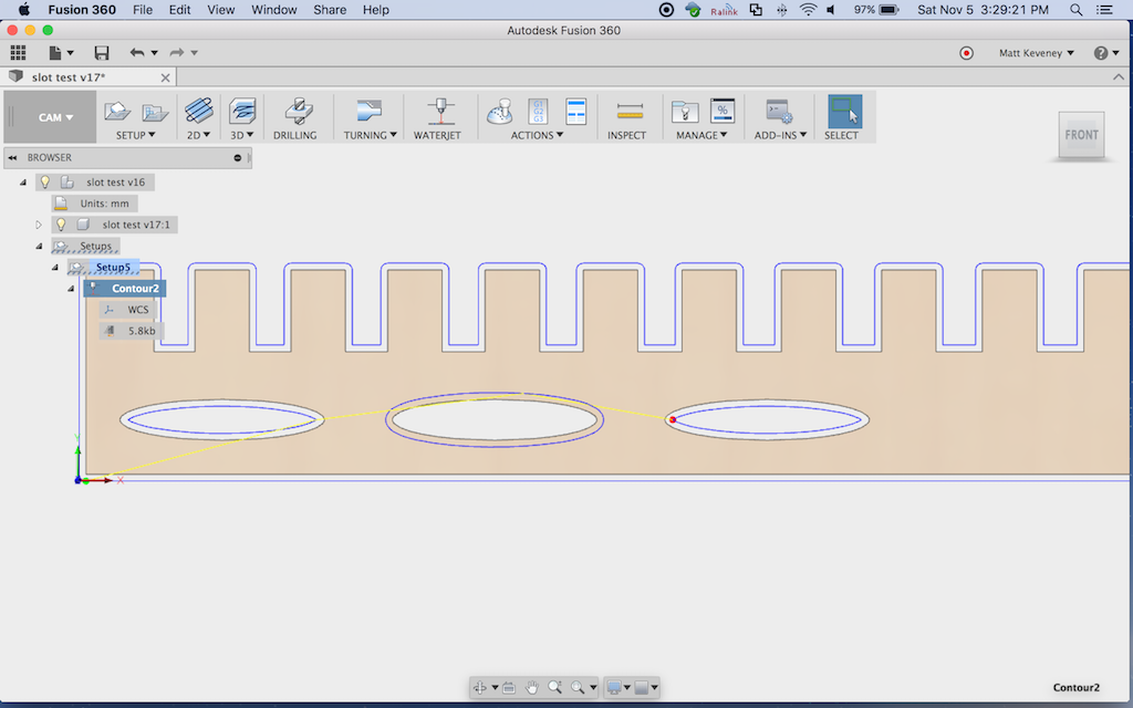
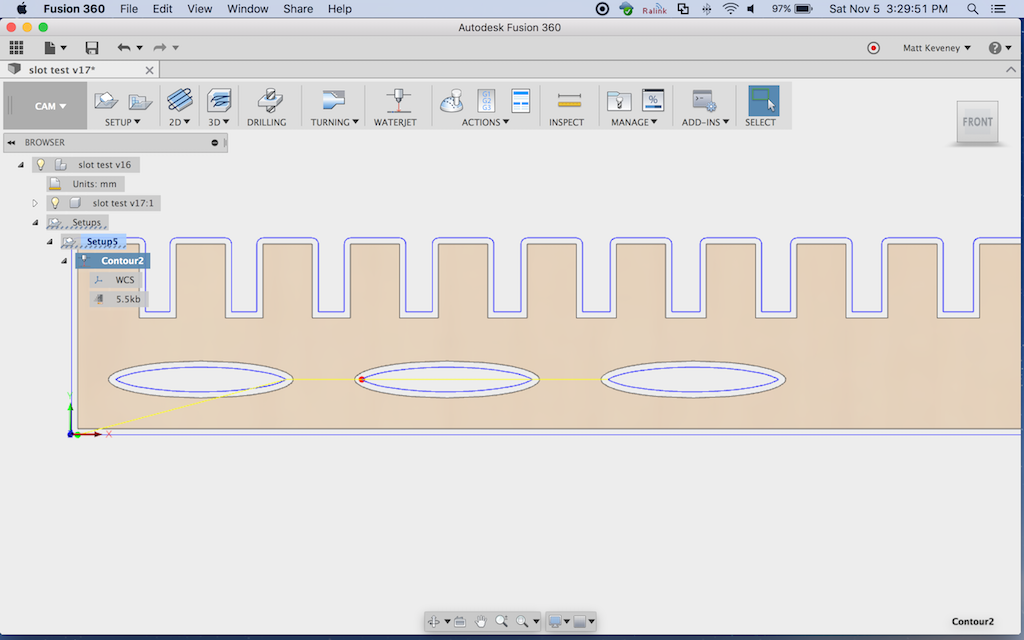
The tool path should be generated immediately. Examine it carefully, and ensure that the paths are all outside the part. For holes, the paths should be inside.

This is what those red arrows are all about. Note that the middle elliptical hole in my example has the tool path incorrectly positioned. To fix it, edit the contour; choose the geometry tab, and click the arrow on the offending contour.

profile-wrong

profile-fixed

When the tool path looks correct, right-click on setup and choose ‘post process.’
Under ‘settings’:

  • Set ‘source’ to ‘personal posts’ (or ‘My Cloud Posts’ if you went that route).
  • Set ‘post processor’ to ‘dxf.cps – Autodesk DXF’
  • Setting ‘units’ to ‘millimeters’ seems to work properly on our laser. You can use millimeters here even if you designed the project in inches.

Under ‘properties’:

  • check ‘only cutting’ This will remove the ‘raise and move’ tool paths.
  • Click ‘OK’ and save your DXF file (probably to your network folder, so you can easily access it from the laser cutter’s computer).

Then, import the DXF into the laser as usual. Everything else is still done as taught in our Laser 101 class.

Note on Kerf

The kerf produced by a laser cutter is not perfectly vertical, it’s V-shaped (wider at the top). The kerf will vary in width depending on your material, power and feed settings.

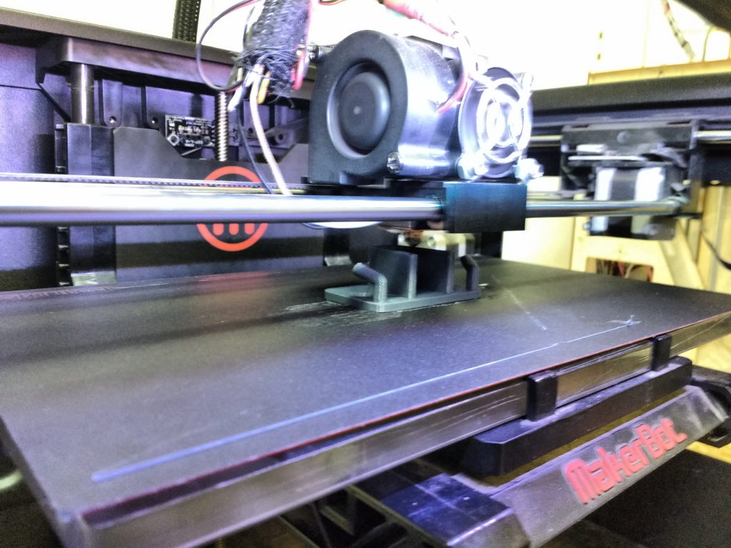
To determine the correct kerf, I recommend cutting a test shape; perhaps a square 20mm on a side. Set the kerf to a reasonable estimate (.2 to .5 mm worked for me, cutting 3 mm baltic birch ply). Then re-generate the tool path and cut using the speed and power settings you will be using for the final piece. If the part measures too small, increase the kerf and retry. If it measures too large, decrease. You should be able to zero-in on the right kerf size for your material’s speed and power settings in just a few tries. Don’t expect perfection, since the kerf can vary even within a single cut due to variations in the material density. I called it good once I got within .1mm.

It should go without saying that you should not scale the cut path inside Lasercut, since that will also scale the kerf adjustment. If you want to make your part bigger or smaller, adjust the model in Fusion 360.

Conclusion

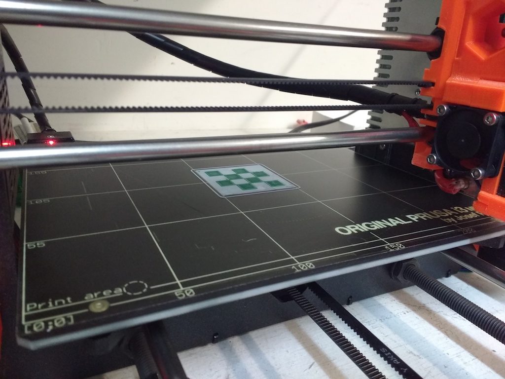
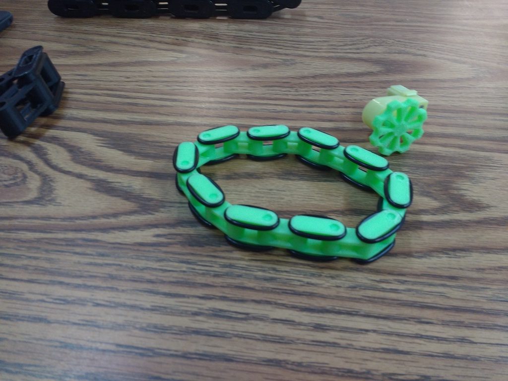
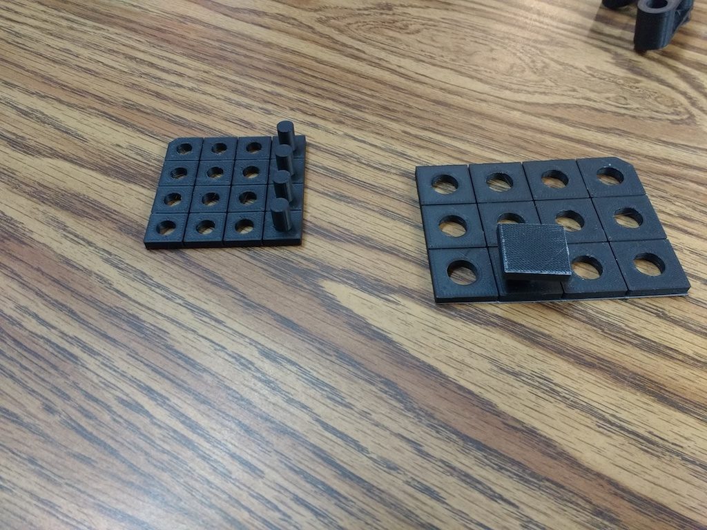
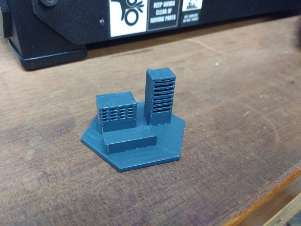
This method should enable you to cut parts to dimensions that precisely match your design. Of course, there’s more to it than that. You have to get the design right to begin with, including appropriate clearances for mating parts. I made the comb-like part illustrated above to experiment with slot sizes; you may want to do something similar with your project.

And I must mention that I don’t think Fusion 360 is the universal design tool for the laser cutter, especially for projects that simply don’t require that level of accuracy.

Designers who identify as artists rather than engineers will probably be much more comfortable with a 2D drawing tool like Illustrator or Inkscape. I recently used Inkscape to model a puzzle project; it would have been a big pain in the neck to do with Fusion 360. Even if you are making parts that must fit together, you can certainly get by with a bit of experimenting, some sanding here and there, and maybe a little extra glue in spots.

I have not yet explored generating separate layers in Fusion 360 for use with engraving or multi-power cutting operations. If you figure that out please write a follow-up post!

Ray came by when I was cutting my first prototype and wondered whether I took care to cut the inside cutouts away before the perimeters. If you don’t do so, the part may fall from the material and shift slightly, causing subsequent cuts on that part to land in the wrong place. I had not done anything special in this regard, but observing the rest of the job, it appears that Fusion did it for me — all interior cuts were performed first. …Or maybe I just got lucky. I’ll ask on the Fusion 360 CAM forum and see if anyone knows.

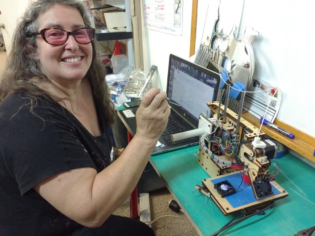
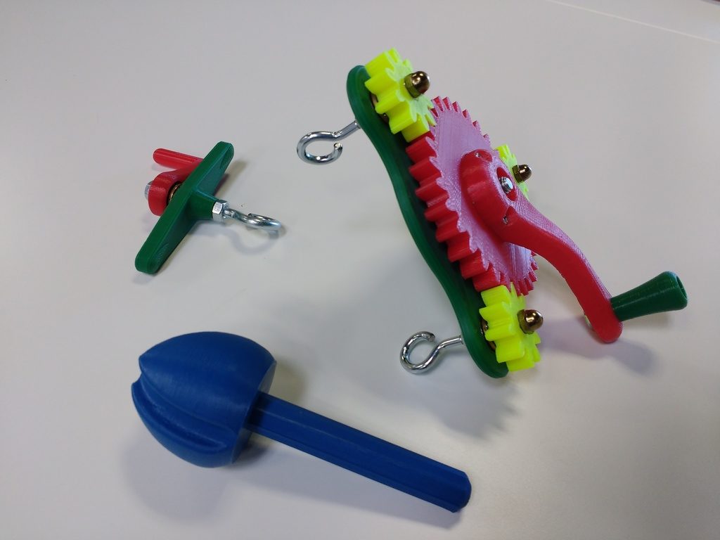
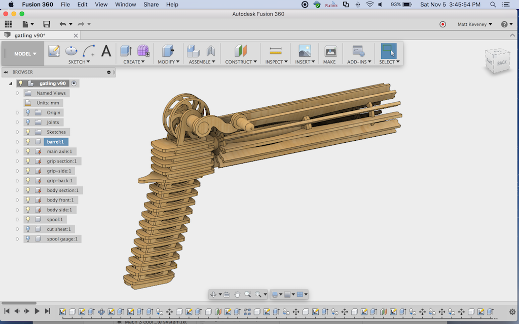
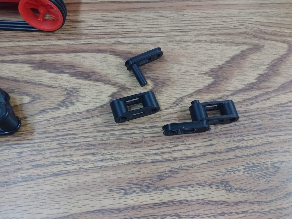
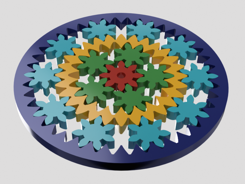
And, if you’re wondering about that cool rubber band gun at the top of the article, I’m afraid you’ll just have to wait for a follow-up post. I have a prototype together, but already have a dozen minor tweaks in mind to make it perfect!

3D Print Hangout, November 2, 2016

At last night’s hangout we had four guests. Two newcomers: Max and Klario; veteran Grant was there, and newcomer Mark, an experienced 3D print user wondering what AMT is all about. I neglected to write a blog post for our last 3d printing hangout (on 10/17/2016), so in this post I cover a few things from that meeting as well.

A former member (We miss you, Will, come back!) donated a 3Doodler pen (the3doodler.com) that has sat unused for months. A few weeks back, Grant asked about methods to fasten 3D printed parts together and I suggested he give the 3Doodler a try. I don’t think it’s really designed for the purpose, but nobody else was using it, so why not?

Last meeting, he reported his results: Spotty, unfortunately, but mostly because the pen seemed to be having some mechanical problems. But the idea still seemed to have merit…

So, as all proper inventors must, Grant has decided to make a better one. He’s hacking together a glue-gun and a 3D printer hot-end. I’m dying to see the result, and I think we should all gang up on Grant and force him to write a blog post on his progress!

3dp-grants-gluegun
3dp-grants-gluegun-closeup

We did the usual printer walk-through last night. We printed a jackknife-style keyring and a weird alien chess piece as samples. We also talked briefly about design, but most of our guests were already somewhat familiar with design processes.

As things were drawing to a close, Mark just casually mentioned that he had a few samples of his work in his car, if we were interested in having a look… I only wish he’d mentioned them sooner! Mark has some really cool robot drive systems, almost entirely 3D printed! I immediately dragged him upstairs to show Ray, who I knew would be interested.

3dp-mike-and-robot
3dp-mikes-robots
3dp-mikes-smaller-tread
3dp-mikes-tread-section

Mark’s tank tread sections use O-rings for traction, and press-fit together with a very satisfying snap. They’re held together by friction, naturally augmented by the ridges the 3D printing process produces. He has designed a few test pieces to get his hole sizes just right.

3dp-mikes-fit-test-pieces

Mark is thinking about joining AMT; I sure hope he does. In any case, I’ve asked (nay, demanded) that he keep returning to share his progress. Please know that our 3D printing hangouts are open to everyone; not just members. Whether you’re completely new to it, or an experienced veteran like Mark, we’d love for you to join us and share in the fun!

Simplify 3D class wrap-up

In place of our regular 3D print meeting, we had a special event last night. Our former 3D print steward, Sean Charlesworth returned to give a class on Simplify3D. Seven members and guests attended.

Simplify3D is an alternative slicer for 3D printing, with a host of advanced features. Sean walked us through the options and demystified all. The customizable support material seems to be the standout feature, and one I’ll be trying soon!

It’s a commercial product, but we have a license for use here at AMT. Next time you have a 3D printing project, give it a shot!

Thanks Sean!

3D Print Hangout, September 19, 2016

Two guests tonight, Dan and Enric. Enric thinks folks are probably still recovering from Burning Man.


3dp-overhang-glasseshook

I started by printing glasses hook version II that we designed last session. I was a bit concerned about the extreme overhang on the little corner retaining pieces, but the printer handled it with aplomb.

I was also anxious to try out the new flexible BuildTak plate Sean recently installed. As the video shows, our results were rather mixed… My part didn’t just pop right off, but removing the plate did make it more convenient to use the spatula.

Unfortunately, I’m still not happy with the design.  After a bit of playing with it, we came up with an even better idea!

Important note: The plate has a distinct high spot near the middle, which may be due to the underlying acrylic sheet. It must be leveled much looser than before to account for this: Level as usual, then back off each knob by a half turn or so, until the center gap feels right. One of our members reported extreme difficulty using high-resolution, since that first layer is so thin. If you have too much trouble, just flip the plate over and use blue tape as before.

3dp-dans-gamepiece

Dan is a newcomer to 3D printing, but came prepared with a few models he’s already made. His first print was a game piece for a board game he and some friends are designing. It printed perfectly on the first try.

A few announcements:

On Meetup I’ve renamed this meeting to 3d Printing Hangout to more accurately reflect what really happens here. Previously we’d scheduled two kinds of meeting, the focus alternating between 3D printer builders and 3D print design. The distinction seemed like a good idea at the time, but it turns out that folks of all interests and levels show up at either meeting, so I thought I’d rename the meeting just to make it clear. Nothing’s really changed.

In place of our next scheduled hangout (October 3) we have a special guest: Sean Charlesworth returns to teach us the ins-and-outs of Simplify3D. Serious 3D-printing enthusiasts won’t want to miss this one:

http://www.meetup.com/Ace-Monster-Toys/events/234203445/

-Matt

3D print meeting wrap-up, September 5, 2016

I think holiday weekends are probably not a good scheduling choice. We had just two guests last night: Andy and Miles. Both are new members.

We did the usual run through on each printer. The Type-A machines printer is up-and-running since it’s recent upgrade, but still exhibits quality issues from time-to-time that I haven’t quite sorted out. Running at a lower-than-usual speed generally tames it for now: say 50mm/second or less.

Andy found a die model on Thingiverse that seemed like a good, simple example. Unfortunately the filleted corners meant we had excessive overhang for the first few layers, resulting in somewhat ragged quality on the bottom face.

3dp-AndyWithDie

Then we found a knight chess piece which seemed like a more challenging test. This one gave us a chance to see what the generated support material was like.

We also spent an hour or so brainstorming with Fusion 360. None of us had any clever ideas for an example model, so I resurrected the ‘glasses hook’ idea that we worked on last meeting. The first design we did had a few areas for improvement, which we tried to incorporate this time around. Unfortunately it was getting too late to print by then; I’ll print it out later and report.

3dp-glasseshook

Tonight Taylor Stein returns for another Fusion 360 training session. This time the focus is on 3D printing, but any Fusion 360 topic will be entertained if there’s sufficient interest. Come if you can! Taylor’s sessions are always popular and well worthwhile.

-Matt

Fun with planetary gear trains

If you’ve seen my websites (here and here) you’ll know that I love mechanical gadgetry. Sometimes the mere mention of a particular mechanism or mechanical problem awakens this obsession, for which there’s no cure but to work out a solution.

Such was the case a few nights back, when a number of us happened to be in the 3D printing/Laser cutter room working on a variety of unrelated projects. In the midst of it all, Cere and I struck up a conversation about an interesting planetary gear mechanism she found on Thingiverse. Here it is:

plg-emmetsBearinghttp://www.thingiverse.com/thing:53451

The designer, Emmett Lalish, is an expert in the nuances of 3D printed design and a prolific contributor to Thingiverse. His projects are very popular and highly recommended.

This mechanism illustrates captured planetary gears that require no carrier. The gears have a herringbone tooth form and are printed in-place, so they require no assembly and cannot be disassembled. The mechanism is an entertaining illustration of the potential of 3D printing, and has practical application as a roller or thrust bearing.

Cere was thinking that it might be an appropriate driver for a kinetic sculpture idea she’s toying with. In her application the ring would be stationary, the sun gear motorized, and the planet gears would drive the sculpture. I hope we can persuade her to blog about the sculpture portion, which sounds fascinating. I must confess that I was more interested in the driving mechanism.

Cere’s idea was to expand Emmett’s design by adding teeth to the outer perimeter of the ring, another set of planet gears and another ring, all driven by the central sun gear. I knew at the time that there would be an additional degree of freedom in that mechanism that would cause trouble, but with everything going on that night I couldn’t clearly articulate my thoughts. Anyway, it’s much easier with illustrations, and was a good exercise to get more proficient with Fusion 360’s assembly and rendering tools.

Here’s my copy of the original mechanism. I’m using simple spur gears for clarity.

And here’s the extension Cere envisioned. The ring becomes a sun gear in a larger version of the same mechanism.

plg-double

The problem here is that the mechanism is not deterministic. The inner ring floats without being positively driven.

For example, the inner ring (yellow in this model) might, due to friction, remain stationary and not drive the outer planets at all, as illustrated here:

Then again, there might be such friction in the inner assembly to make it revolve as a unit, driving the outer planets as expected but without properly turning the inner planets about their axes, as illustrated here:

In practice the result would probably be a inconsistent mixture of the two, with erratic motion in fits and starts. What we want is a mechanism that smoothly revolves all the planets about their axes while they orbit the sun gear. Here’s what I think Cere really wants:

From this we can see that the inner ring must somehow be made to turn at a particular ratio with respect to the rest of the mechanism. I’m sure there are many ways to do this, but the most appealing to me is to create another sun-and-planet mechanism beneath this one! The carrier of this driving layer is fastened to the inner ring gear of the main mechanism. The upper mechanism then behaves as desired.

Of course, there are simpler mechanisms that might meet Cere’s needs. Perhaps the easiest modification is to just enlarge the sun gear so we could accommodate more planets.

Here’s a gear train that contains a series of planet gears in a sort of pinwheel arrangement between the sun and ring. We will need a carrier in this case, and some of the planets revolve in the opposite direction, but we don’t need a two-stage device.

It’s been fun exploring the options. If you’d like to know more, here’s a good explanation of planetary gear ratios and how to calculate them:

http://woodgears.ca/gear/planetary.html

To model the gears, I have a Fusion 360 add-in installed. I can’t remember whether Fusion came with it or I installed it later… In any case, I modified it to suit my needs, which might be a good blog post in its own right.

I hope this has inspired you to come up with your own mechanisms! Please blog about it if you do.