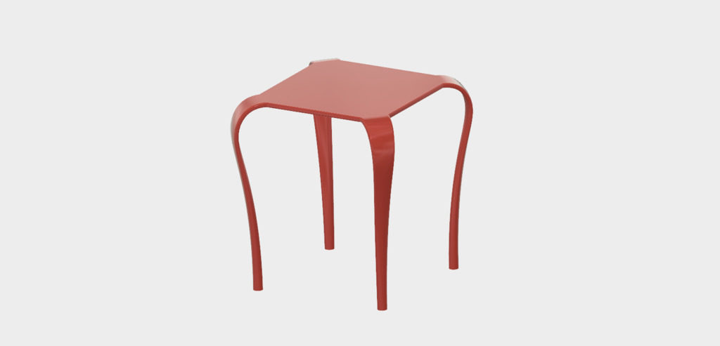
On Monday, Chelsea came to me with a question about Fusion 360’s loft tool. I was unable to give a quick answer, so later I practiced a bit by making an approximate copy of the design she was working on. As I was looking it over, I found that it also illustrated a few ‘best practices’ I’ve cultivated that I think make my designs easier to edit and maintain. Chelsea has given me permission to share them with you here.
The project is an end table with legs that gracefully descend from a simple square top. The legs emerge from the corners of the table, bend downward, and transition to a circular section at the feet. Imagine four angry Cobras swallowing the corners of the tabletop!
The legs look like a job for Fusion 360’s Loft tool. Since this loft must follow a curved path, we’ll need either centerline or guide rails, and a bit of planning to make it come out right.
Here are the steps I took. You may follow along and recreate it, or merely inspect my design linked below. This is not a tutorial for complete newcomers: I gloss over the keystrokes and mundane details. I think it will be worthwhile reading anyway. The sooner you adopt habits like these, the faster you’ll become productive with Fusion.
First sketch the tabletop on the horizontal plane which is X/Y in my configuration. Note that I’ve deliberately put the sketch origin in the middle of the tabletop. Since this tabletop is symmetrical about its center, this may come in handy later.

Note also that I’ve managed to fully constrain the sketch using just two dimensions (and a lot of other constraints). I’ve chosen dimensions that define the features that I may want to alter later: the overall width of the tabletop and the width of the corner faces.
Keep your sketches tidy!
When helping folks out with Fusion, I see a lot of messy sketches. I think the best sketches have no more detail than needed to support their associated operation, are fully constrained, and clearly express the design intent.
Above all, do get in the habit of fully constraining your sketch every time you edit. You should not be able to drag a line or curve out of place.
This is especially important in Fusion 360, since it’s possible to jog sketch elements around without first opening the sketch for edit. When selecting an unconstrained profile to be extruded or revolved, it’s way too easy to bump something out of its intended location. I think this is a terrible feature of Fusion, but if it disciplines you to constrain your sketches, perhaps it’s ultimately a good thing!
Here are a few other things I try to avoid:
Duplicated dimensions
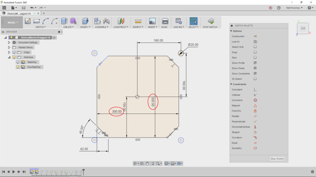
If two features are the same length, use the equal constraint instead, or at least reference one master dimension from the duplicate. This way, you’ll be able to change the dimension in one place.
Dimensions on the wrong things
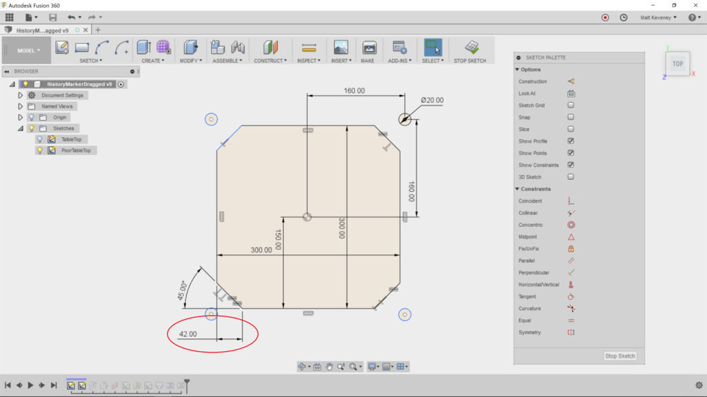
The corner edge could be constrained by defining a distance from the cutoff corner, but this does not seem like the most natural choice. If I were describing this table to a friend or client, I would rather say “the legs are 60mm wide at the top” than “the legs descend from edges that were cut 42mm from the corners.” This is my guiding principle when choosing which features to dimension: Would I describe it to someone else in the same terms?
A dimension where a constraint is more appropriate
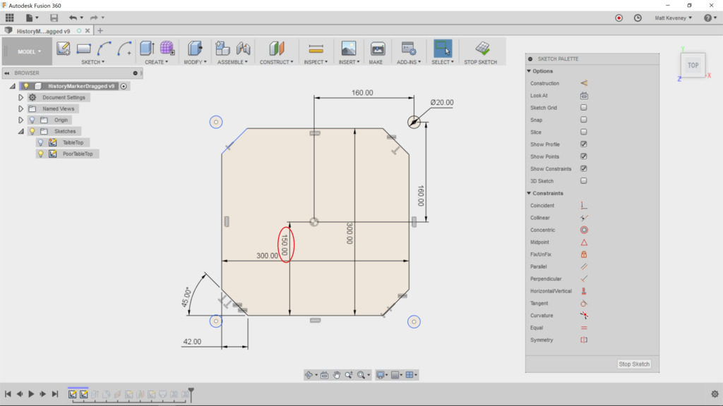
Here the top has been centered by specifying dimensions one half the width of the tabletop. Using a pair of construction lines constrained to the midpoints clarifies the intent, and eliminates a step if we ever want to resize the table.
Unconstrained geometry
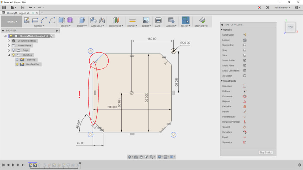
A few of the edges appear to be correct, but have not been defined. It may look okay on screen, but if you render this design with a CNC machine or 3D printer, the part dimensions will be incorrect.
If you’re transitioning from an older CAD or illustration program that relies on a ‘snap grid’ to align points, break that habit now! The grid may be convenient for drawing something in approximately the right size, but it does not constrain your sketch geometry. I recommend you turn the grid off and never look back.
Note: Fusion tries to display unconstrained geometry in blue, and constrained geometry in black. Unfortunately this feature is riddled with bugs! I’ve seen countless cases where partially constrained geometry is displayed in black, like the left vertical edge of this sketch. Beware!
Superfluous geometry
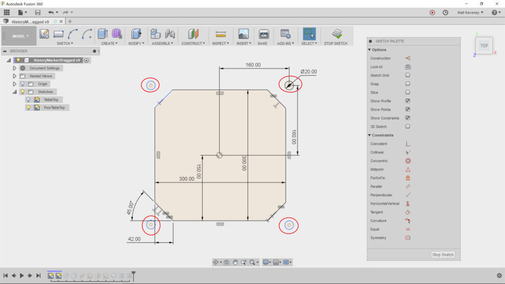
The profiles of the feet have been defined in this sketch as well, even though those profiles will not be used when extruding the tabletop. I see this a lot. The designer may be thinking in terms of old-fashioned blueprints, which were intended to communicate a design. A top-view drawing of this table would generally illustrate the position of the feet, and would probably show the shape of the legs from that perspective too.
Sketches in Fusion are for defining the design, not for communicating it. Each of these features should be defined in a separate sketch. If you need a drawing, create it with the ‘drawing’ feature after the model is complete.
Just before closing any sketch, always try modifying a dimension or two, just to make sure the sketch resizes as you expect:
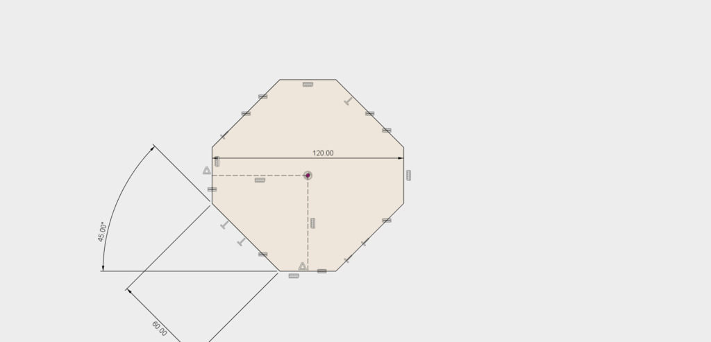
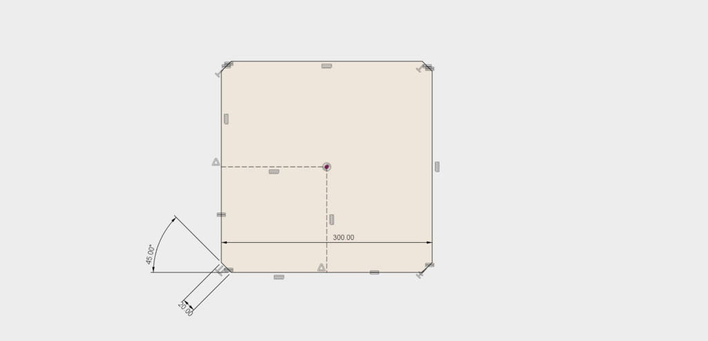
Now back to the model. Save the sketch and extrude the tabletop. I’ve chosen a thickness of 10mm.
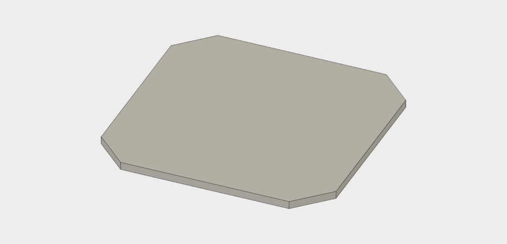
Now we need to create a construction plane on which we’ll sketch a loft center-line. We have a lot of choices here: we could use the ‘Midplane’ tool, choosing two opposite corner faces, or we could use the ‘Plane at Angle’ tool, using the central vertical axis and an angle of 45 degrees.
In this case, I prefer the ‘Plane Along Path’ tool, selecting the upper edge of one corner as the path. The distance must be set to 0.5 to position the plane in the middle of this edge. Since it’s defined relative to this line only, the plane will remain in the correct place even if we decide to make the tabletop rectangular instead of square.
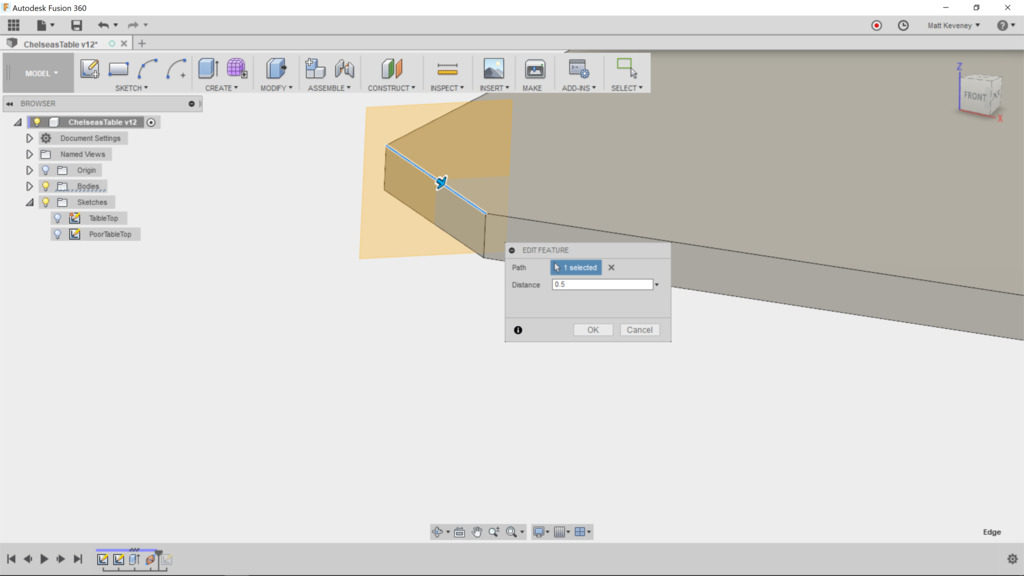
Create the sketch on this plane and project the corner edge of the table that we’ll be lofting from. This is the only projected feature we need, so I like to hide all the bodies at this point. I also hide all other sketches. This prevents inadvertent projection of other edges we don’t need to reference, and makes it clear which lines/features are actually in the sketch we’re editing.
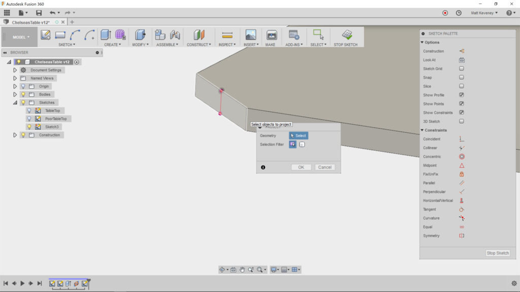
I think Fusion’s auto-projection features can do more harm than good, especially for newcomers. If you’re not careful they will add extraneous and confusing cruft to your sketches. Do your sketches contain lots of purple lines and points that seemed to spring from nowhere? Consider turning these two features OFF, at least for a while:
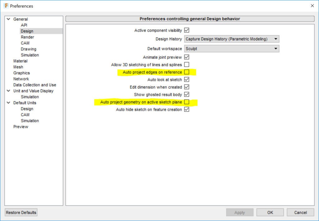
With these disabled, you’ll have to explicitly use the ‘project’ command to project an external edge into your sketch, so you’ll always know when it happens. Once you get the hang of it, you may want to turn these time-savers back on, though I’ve never liked the second one. I think it adds way too much unnecessary guff to my sketches.
Now on with the sketch. First of all, I like to convert the projected line to a construction line, since it doesn’t really participate in defining the new profile or path I’m creating; it merely serves as an anchor to keep the new geometry in the correct relative position. Create the center line as a spline through just three points.
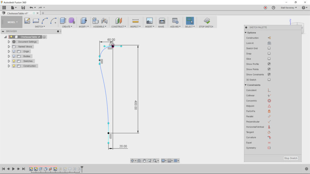
Note that I’ve constrained some aspects of the spline but not all–a rare case in which I intentionally choose not to constrain everything.
- The position of the foot of the leg is defined in relation to the corner edge of the table.
- The upper end of the spline is attached to the midpoint of the projected edge, since we want it to spring from the middle of that profile.
- A horizontal/vertical constraint is applied to the upper endpoint’s ‘control handles,’ so the the end of the curve will be perpendicular to the existing face. Another at the bottom makes the leg end perpendicular to the floor.
- The middle control point’s horizontal distance from the table edge is defined so that this distance is maintained even if we change the size of the table. By fixing this control edge vertical, we ensure that this dimension defines the outermost edge of the curve.
I like to leave the remaining aspects of the spline fluid. This shape seems to be an organic element the designer creates by eye. We could use the ‘fix’ tool to constrain the curve once we have it right–something I would generally advise. In Fusion, doing so interferes with resizing the tabletop, so I like to leave it fluid.
Note: What I really want here is some kind of ‘relative fix’ tool that locks the curve in relation to a specified sketch point, but Fusion doesn’t seem to have any such thing. Fusion’s ‘fix’ tool fixes the curve in absolute 3D space, which is admittedly easier to understand.
Now we need a sketch defining the bottom profile of the leg. Since we have no existing face there, we first create a construction plane.
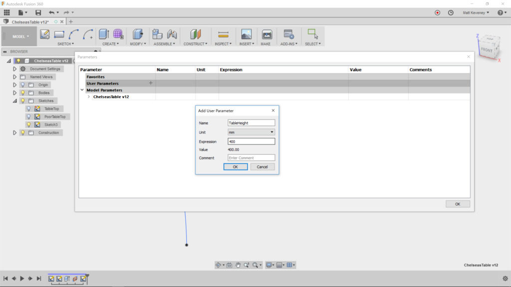
But let’s think about this a minute! This plane should always be the same distance from the tabletop as the corresponding dimension in the centerline sketch. We can achieve that by defining a parameter and using it in both places.
Create a parameter called ‘TableHeight’ and set it to 400mm.
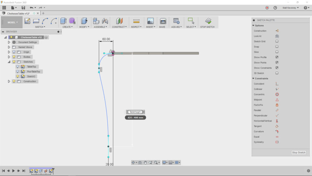
Then edit the centerline sketch and change the height dimension to ‘TableHeight.’
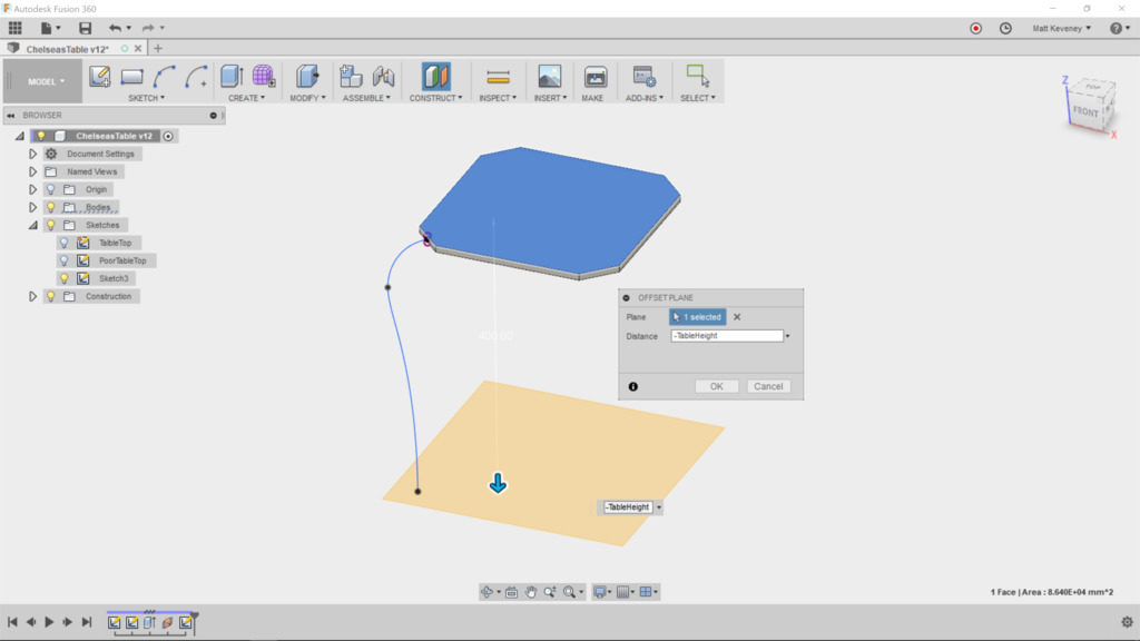
Now, finally, create the offset plane, referencing the top surface of the table, since that’s the point we measured from in the sketch. Set the offset to ‘TableHeight.’
Now create a sketch on this new plane. With the centerline sketch visible, project the lower point of the centerline into our sketch. Hide the centerline sketch now, so it doesn’t distract us. I’ve chosen to just create a circle centered at the projected point and dimensioned to 20mm. Whatever shape you choose, it should be centered on this point, since the centerline is expected to pierce the center of the loft profiles.
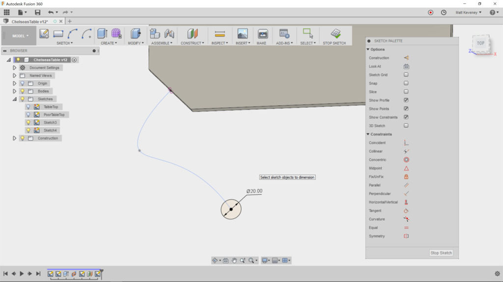
Finish the sketch, and turn on visibility of the centerline sketch and the bodies again.
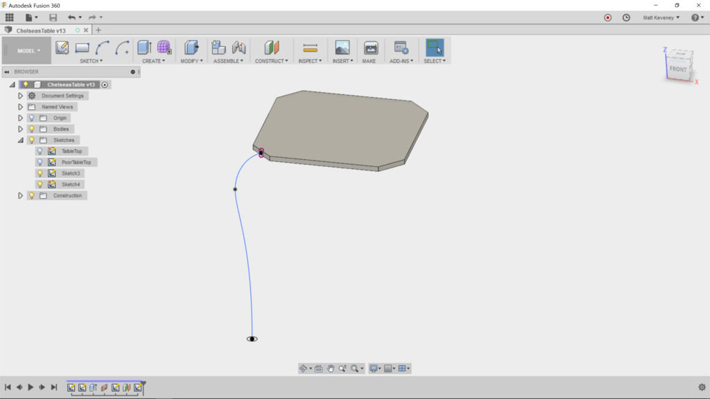
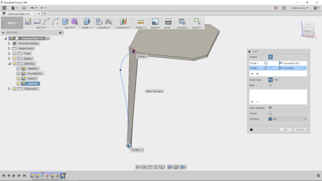
Now, we can create our loft. Choose the corner face of the table as the first profile; the foot sketch profile as the second. A weird-looking loft will be displayed since we haven’t yet applied the centerline.
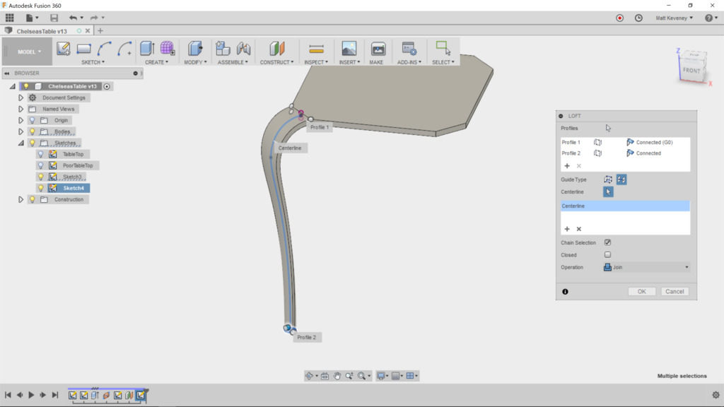
Choose the centerline guide type, and select the spline from the centerline sketch. The loft should now appear as intended.
Finally, we duplicate the leg for the other three corners. Since our table is square, we could simply use the circular pattern feature. Select ‘feature’ as the pattern type and choose the loft feature from the history list at the bottom of the screen. Select the vertical axis as the axis of revolution. I told you that would come in handy! Set the count to 4, and our basic design is complete.
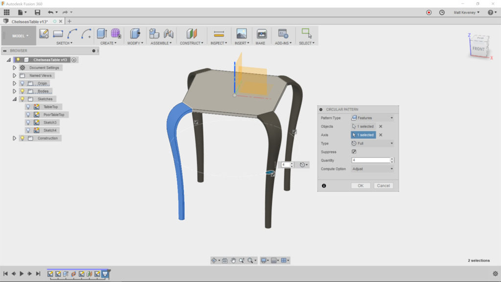
That’s fine, if we know we’re always going to want the table to be square. To make our design a more flexible, let’s use the ‘mirror’ feature instead. We’ll need to use it two times; one for each direction.
First, right click and delete the ‘circular pattern’ feature in the timeline.
Select the mirror tool; set the pattern type to ‘feature’ and choose the loft feature as before. Then choose ‘mirror plane’ and select the X/Z plane.
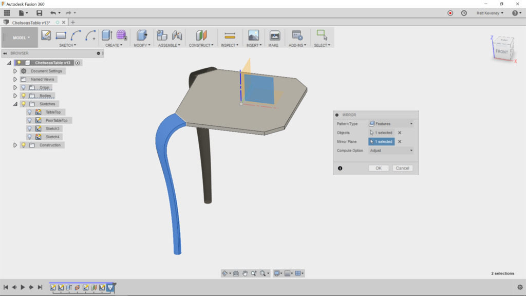
Now, create another mirror. Again, select feature type, but this time choose two features from the history list: the loft and the mirror we just created. Use the Y/Z plane as the mirror.
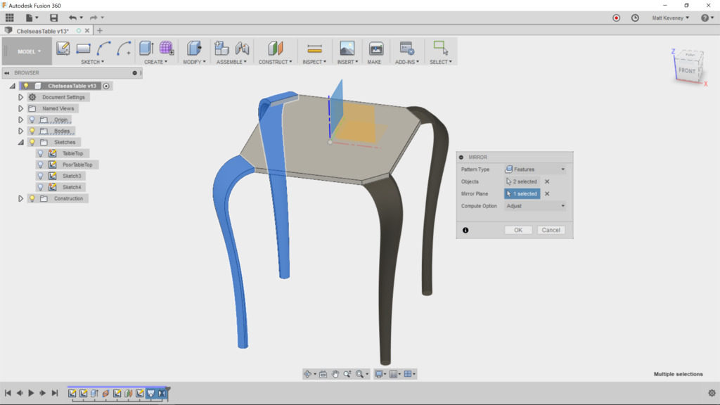
We get the same result, but we get the additional flexibility of making the table rectangular, which we’ll explore below.
First, let’s break those sharp edges. The fillet tool is what we want, but applying it to those complex lofted edges is computationally intensive and doesn’t always produce smooth results.
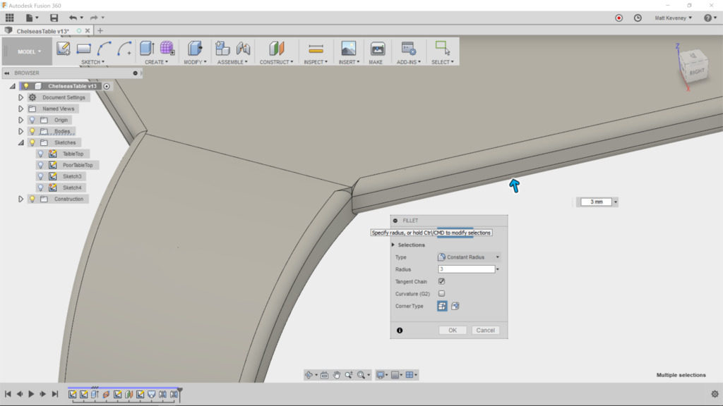
What we really wanted to do was to round over the tabletop edges before we lofted the legs. This way the loft would be created from a face that already has rounded corners. Fortunately, we can rewrite history with Fusion.
Drag the history marker to a point just past the extrude feature that created the tabletop. Now, select the fillet tool and round the edges that will end up exposed. do not round the edges at the corners, but do select both top and bottom edges, like so:
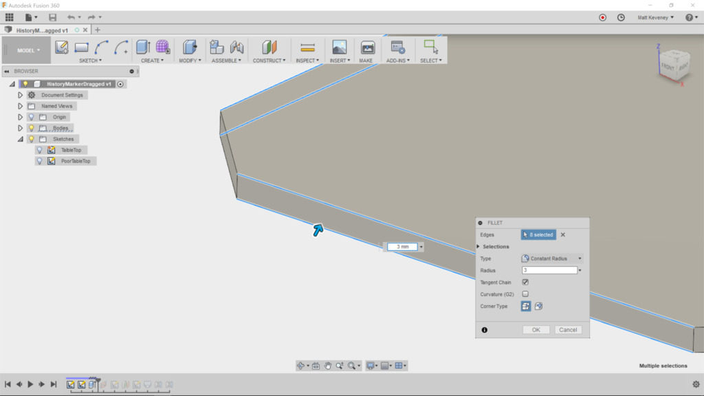
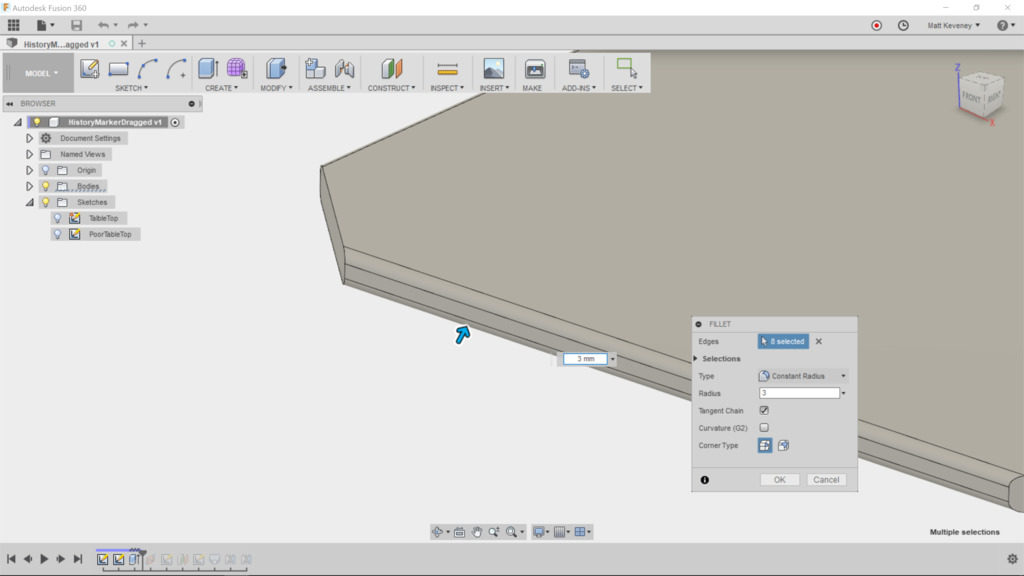
Now move the history marker back to the end. The legs now blend with the tabletop as intended. I’ve given it a glossy-plastic material.
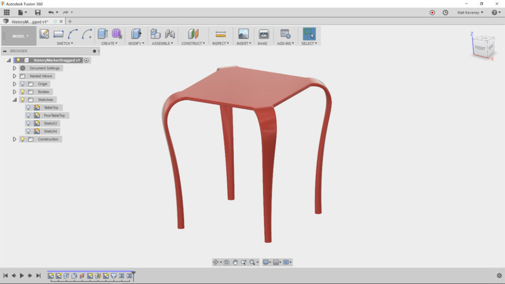
Let’s try out a few parametric features, to see if our extra work pays off. Change the table height by adjusting that parameter we created.

Changing the size of the feet gives the table a whole new character.
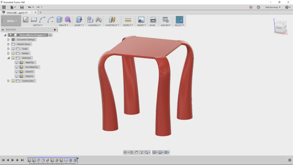
(If you expect frequent changes, it might be handy to create additional parameters for the table width, upper leg width and lower leg diameter. Then they could all be modified in a single place. I’ll let you play with that on your own.)
Change the thickness of the table by editing the first ‘extrude’ feature. It yields expected results, since we defined our table height referencing the table top, and attached the loft centerline to the midpoint of the table edge.
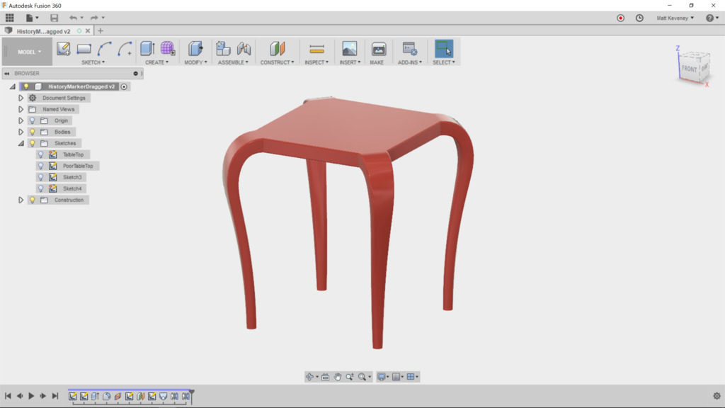
Finally, let’s make the tabletop rectangular. Edit the tabletop sketch and remove the ‘equal’ constraint currently applied to the lower and left sides. Now add a dimension defining the distance between the horizontal edges. Change the dimensions to 450 horizontal by 300 vertical.
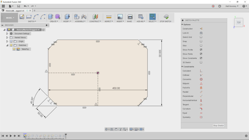
After saving we get this:
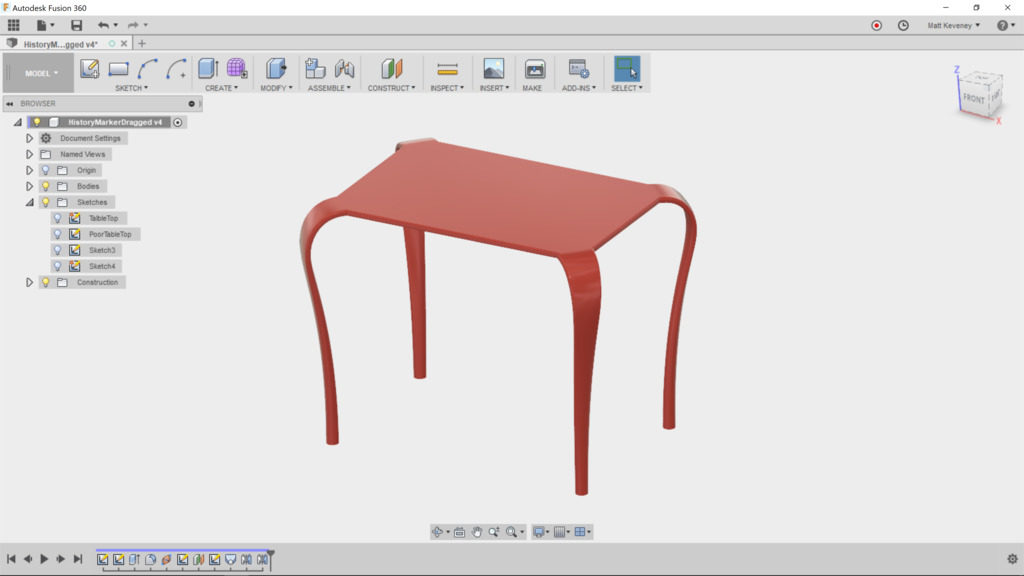
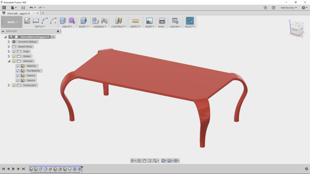
By changing just a few parameters, we can make a wider, lower, coffee table to complement our end-table.
Thanks for reading this long-winded article all the way down to here! To get the most out of Fusion, learn to use the parametric features, and use them wisely. Neglecting them or using them inappropriately can make your designs difficult to alter later, and believe me you will always want to alter your design later. The important thing is to consider maintainability as you go along.

