Author: Matt Keveney

3D printing steward, CAD geek, software engineer, and technological history buff.

History editing in Fusion 360

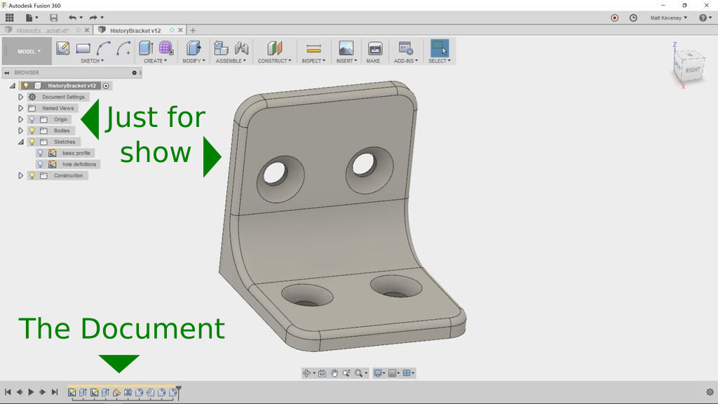
The 3D View is “Just for Show”

With most editing tools, the document you’re editing is comprised of the things displayed right in front of you. With a word processor, it’s the words; a spreadsheet, it’s the numbers and formulae; an image editor, it’s the pixels. This is also true of mesh-centric 3D modelers like Blender or SketchUp. When you move edges or faces, bore holes, or perform any other operation, you’re modifying the Mesh: a collection of points, edges and faces in Cartesian 3D space. The mesh itself is the document.

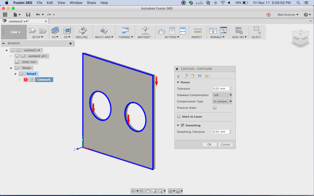
But with Fusion 360, the document is composed of the sequence of things in the history timeline (shown at the bottom of the screen). The 3D view in the center of the screen is the result of executing that sequence of operations. The things in the Browser (the hierarchical object list on the left), are also a product of the history timeline sequence. Think of the timeline as the program code that produces your design. As far as editing is concerned, the Browser and 3D view are just for show!

I’ve always thought that ‘history timeline’ was a misleading name. ‘Operation Sequence’ might be better. In real life we can’t yet travel back in time, so the term ‘history’ suggests that it’s merely an informational record of what already happened. Not so! Items in Fusion 360’s history timeline can be rearranged and edited. Learning how to do so is key to getting the most out of the tool.

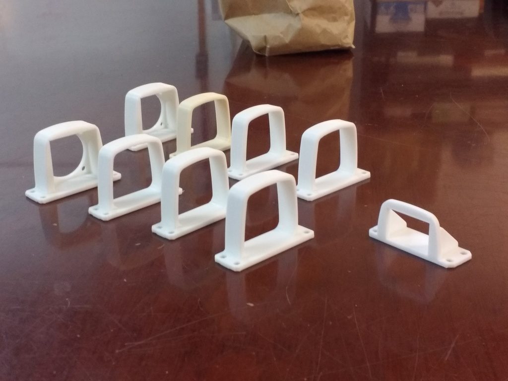
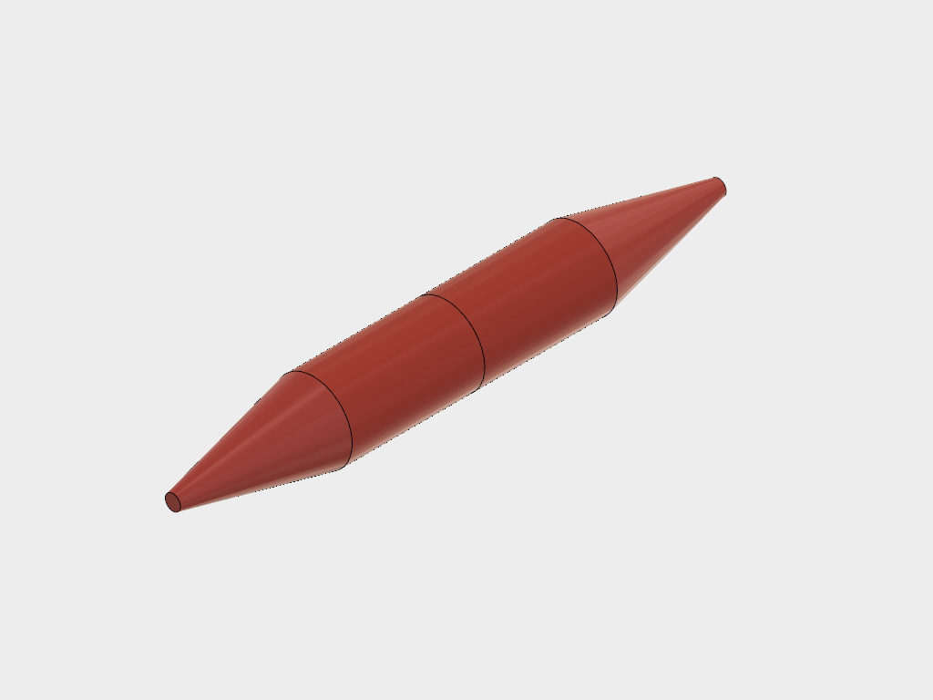
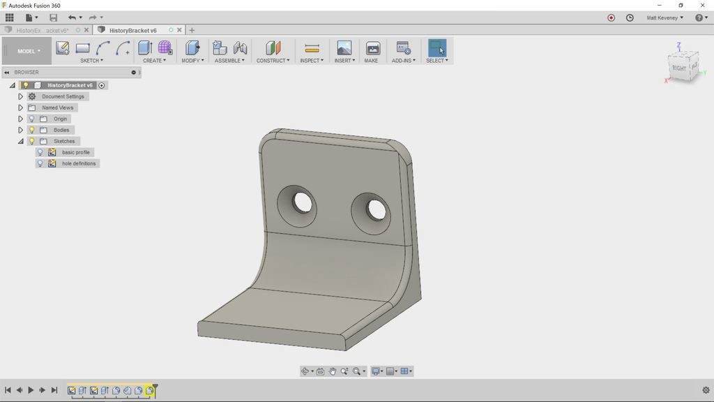
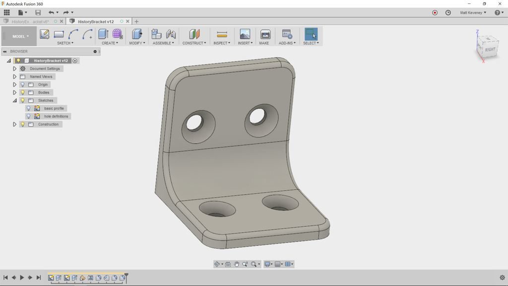
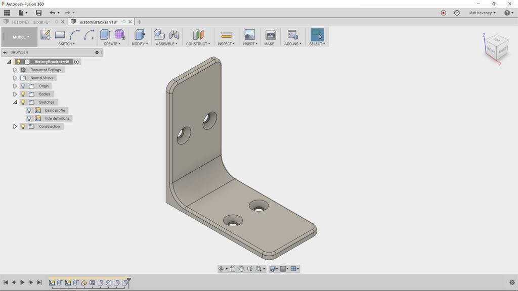
To get some practice with the timeline, let’s walk though a (somewhat contrived) example: The corner bracket pictured above.

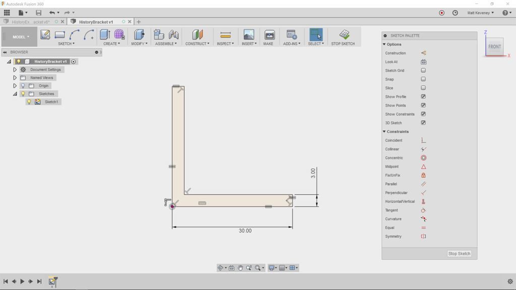
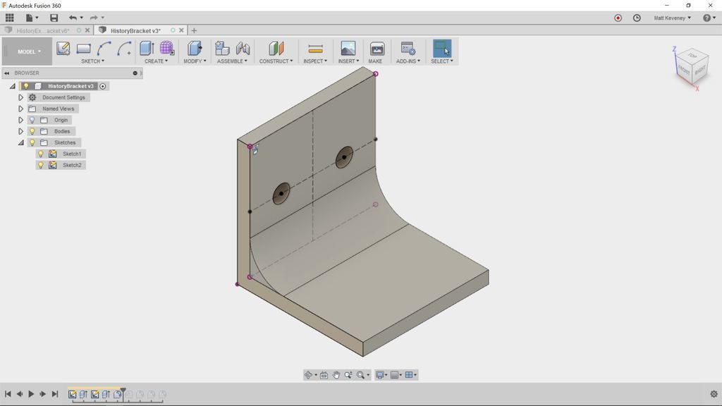
First create a sketch describing the basic cross section profile.

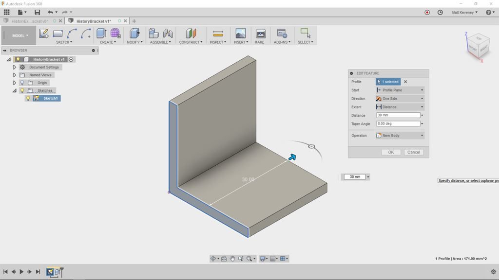
Then extrude with the push-pull tool to create a solid body.

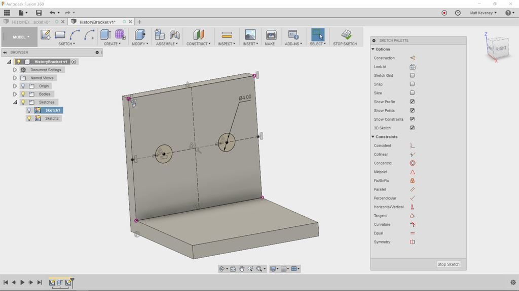
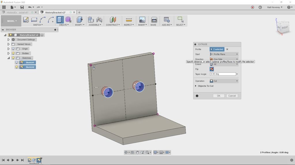
Now create a sketch on one of the sides to describe mounting hole profiles.

And extrude to bore the holes.

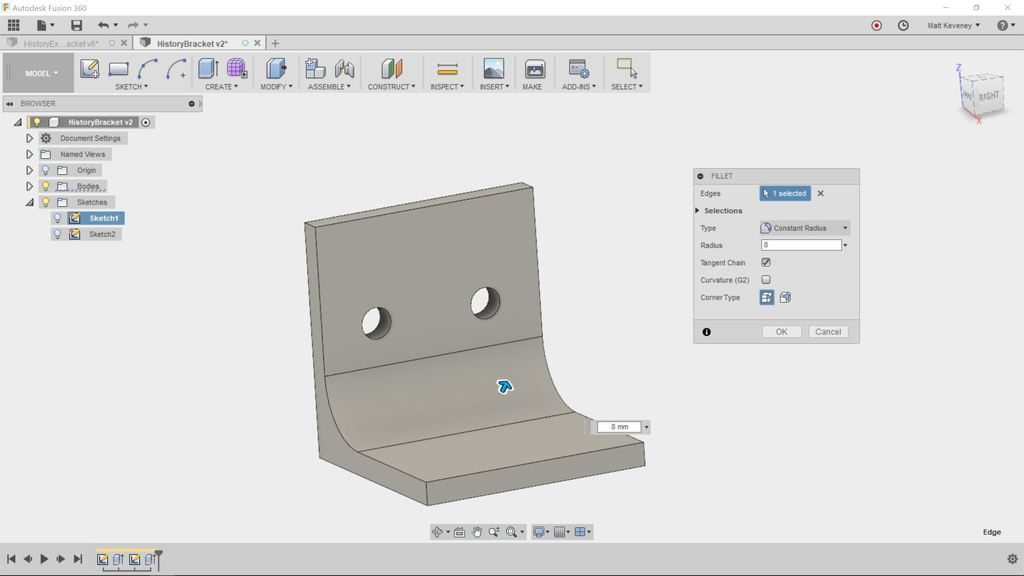
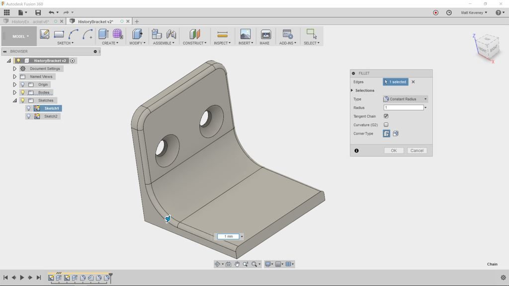
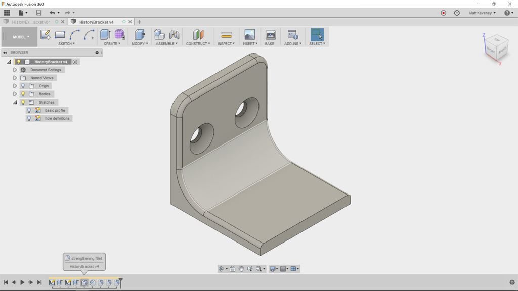
Now, we’ll use some of the modify tools. First, add a large fillet to strengthen the bracket.

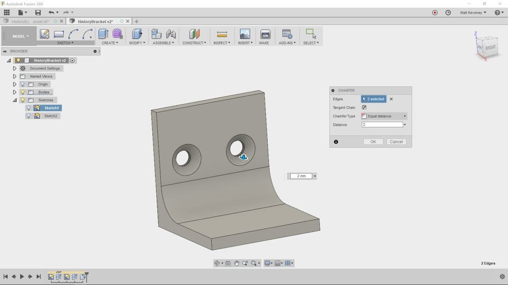
Add a chamfer to counter-sink the holes.

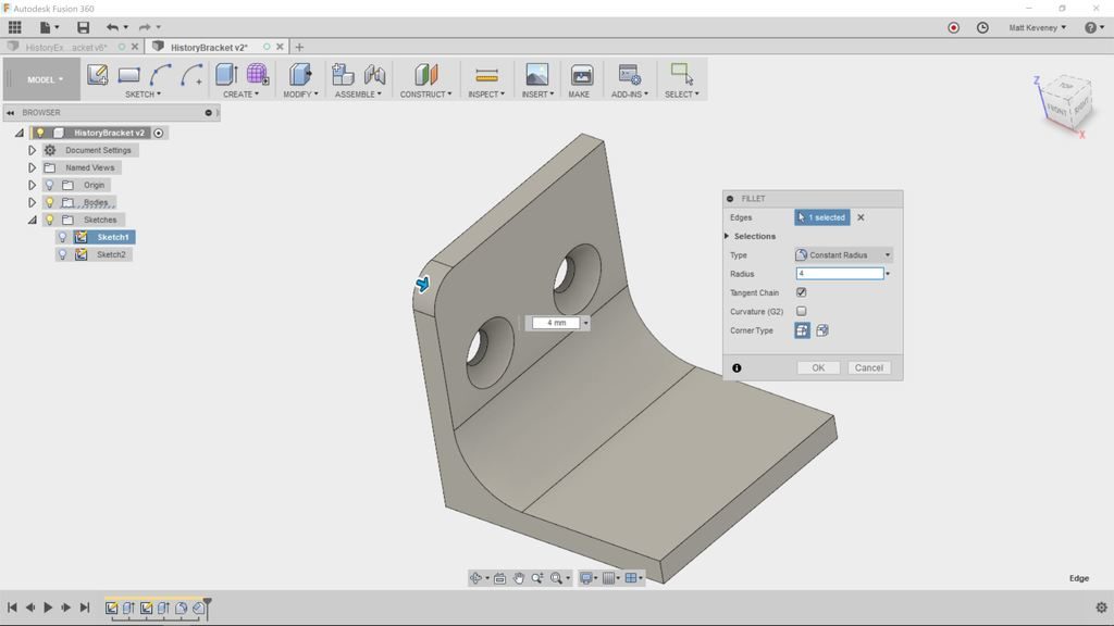
A fillet to round over the top corner.

Add another for the other top corner.

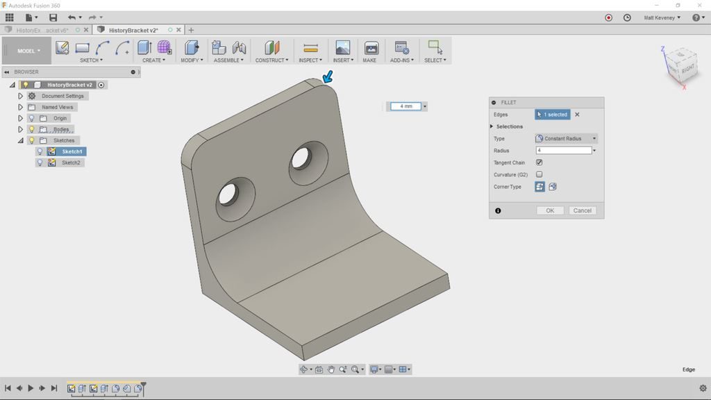
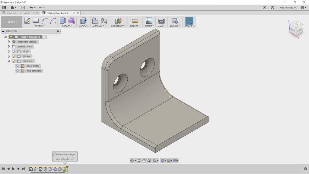
Add one more small fillet to break the sharp edges.

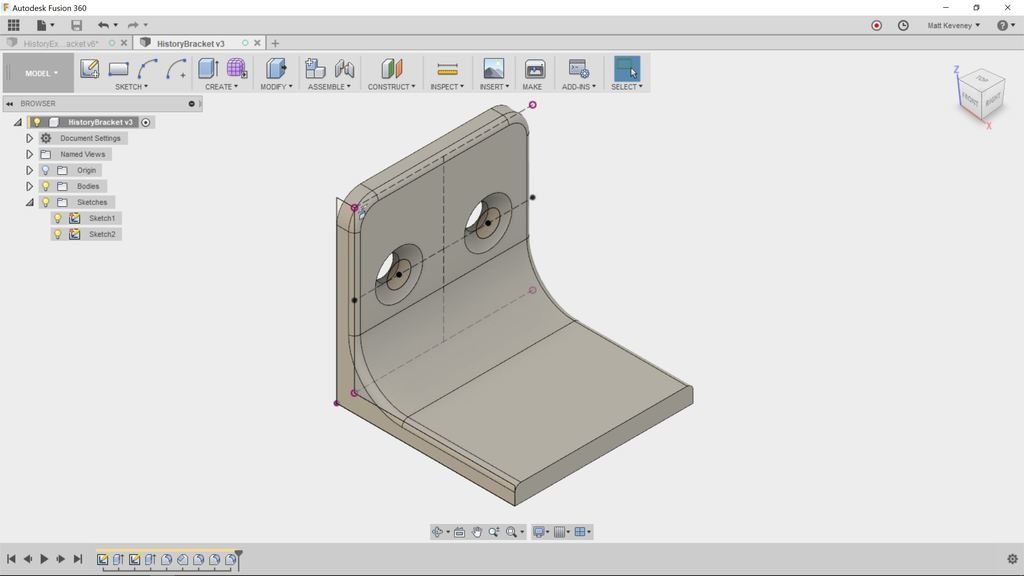
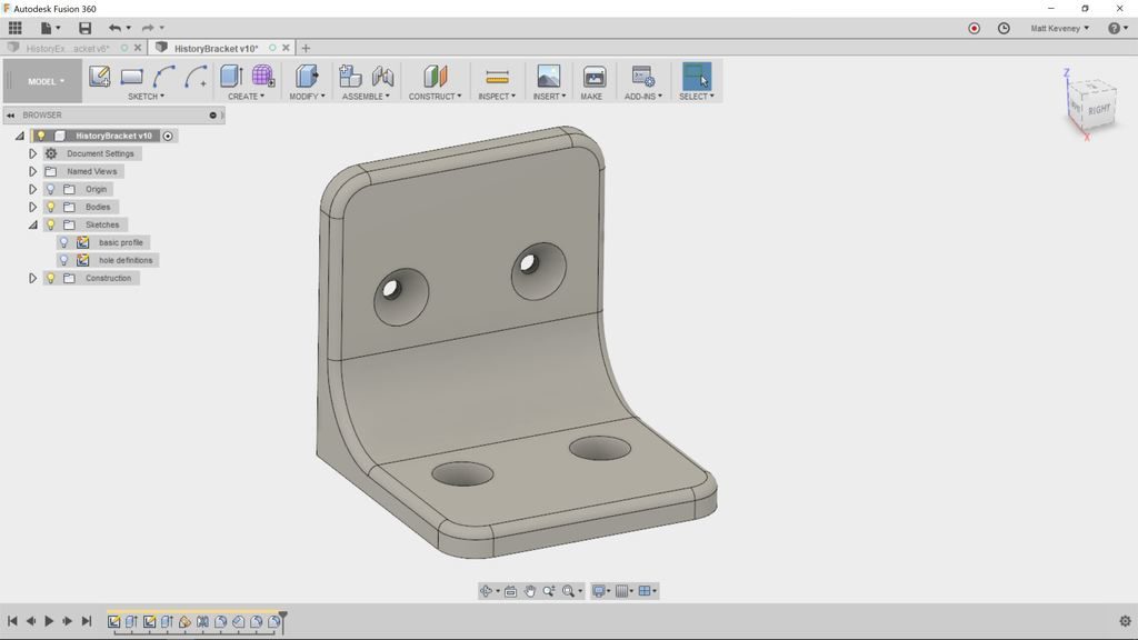
Well, it clearly needs some work, but let’s review the timeline to see what we’ve done so far. First, make the sketches visible for clarity’s sake (find the sketches in The browser and click the light bulbs). Then click the home and fit buttons to get this view:

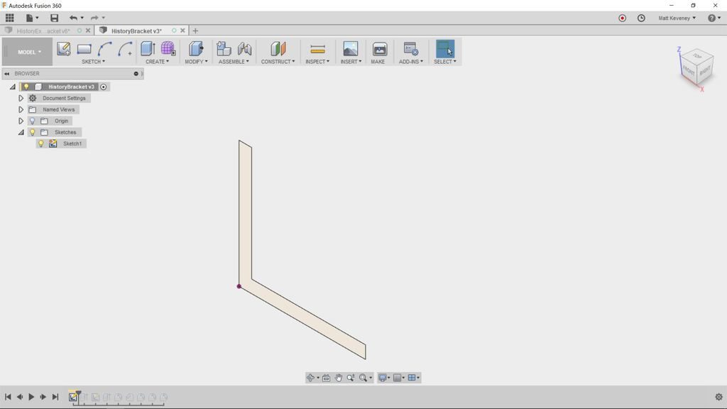
Right click the first item in the history (a sketch) and select Roll history marker here. The body will vanish from the 3D view, and the Browser will display just one object; the sketch. Don’t panic; you haven’t deleted anything! Note that the items in the history are still there; they’re just grayed-out.

You’ve moved the history marker to display the model as it was defined at this point. Remember: the history timeline is your document; the 3D view and Browser are just for show.

Click the next step icon to advance the history marker. With each click, the display will update to reflect another operation. When you reach the end the 3D view will reflect the model as defined so far.

We can give the sketches and features more meaningful names. This is a good practice in any case, but is especially useful when getting familar with the history timeline.

Right click each item in the timeline; click rename and enter the following names:

basic profile
basic body
hole definitions
holes
strengthening fillet
countersinks
corner roundover
corner roundover 2
break sharp edges

To see the names you’ve just entered, hover the mouse over each item in the timeline. The names for sketches also appear in the Browser.

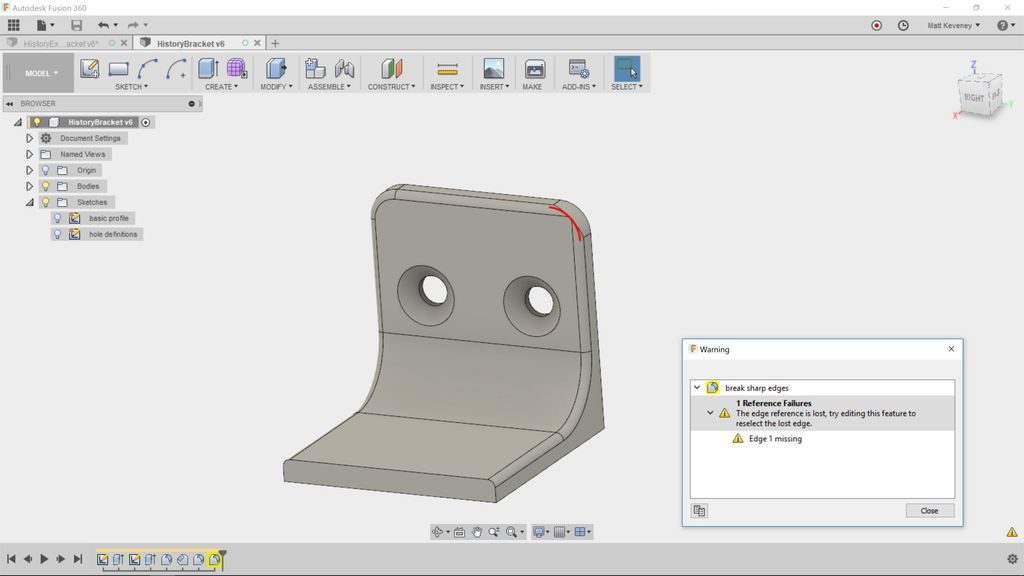
While labeling our history items (sketches and features), I remembered that we rounded the outer corners with two seperate features. It makes more sense to use a single feature, since both of these fillets should always be the same size. That way, if we ever want to change the size we need only edit one feature.

Right click the corner roundover 2 feature and delete it. Fusion will warn that the feature is referenced by other features in the timeline. Click Delete anyway!

Now the break sharp edges round-over feature has a yellow background, indicating that something is amiss. Ignore this for now, we’ll come back to it.

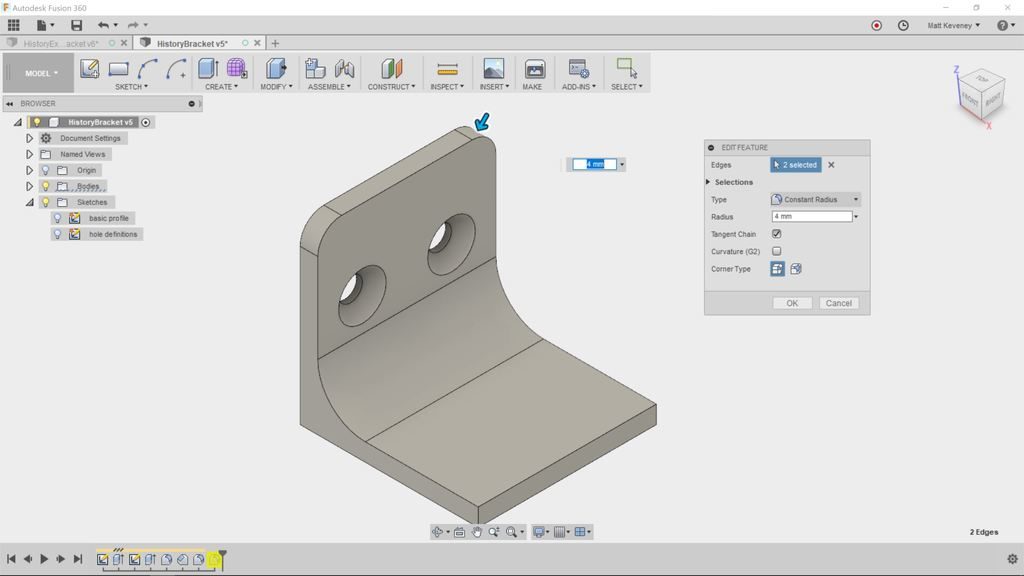
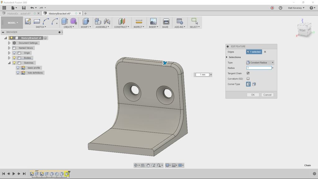
Right click the corner roundover fillet and select edit feature (or just doubleclick the feature’s icon). The fillet dialog will be shown, and the 3D view/browser will reflect the model as it was defined at that point in the history.

The fillet dialog indicates that a single edge has been selected. Hold shift and select the other upper edge. Then release shift and click OK.

Notice that the break sharp edges round-over hasn’t been applied to this new fillet. This is due to the same issue that arose when we deleted the corner roundover 2 feature.

So, let’s have a look. First, right click and choose review warning. This displays more detail about what went wrong. In this case it says: “The edge reference is lost, try editing this feature to reselect the lost edge.”

So, let’s try editing as suggested. Double-click the feature to edit.

Even though the model has the same shape as before, the underlying edges that define the body have changed due to our upstream edit. Notice that it now says two edges were selected (originally there was just one chain of edges). If you press shift these edges will be highlighted. You can clearly see a gap where the redefined fillet is.

Click the ‘X’ next to edges in the dialog box to deselect the edges; then reselect the edge. It will select the entire edge chain again. Once saved, the yellow warning background will disappear.  Be sure to address all warning issues in your timeline! If ignored, they’ll just cause trouble later.

When editing something in the history, we often have to review and adjust downstream features like this. This can be very frustrating if you aren’t familiar with the timeline. With a little practice it becomes second nature, and is a worthwhile skill to attain sooner rather than later.

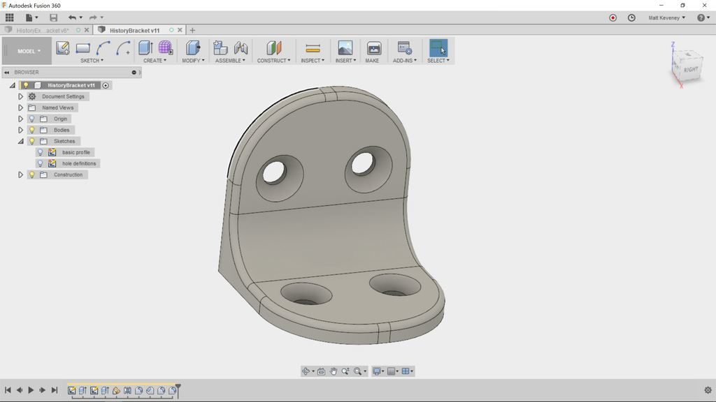
So, let’s finish our bracket. We need holes and round-overs on the other tab, and our break edges fillet needs to go around the entire perimeter.

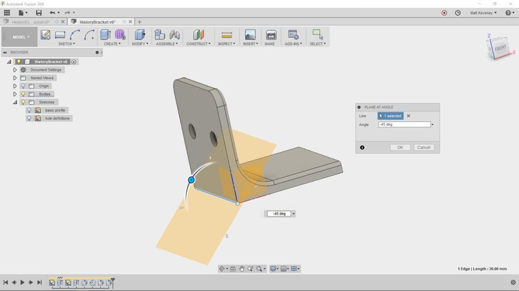
We’d like the hole pattern to be identical on both tabs of the bracket. We could duplicate the sketch and extrude operations that we used on the first tab, but if we ever changed the pattern (maybe to use more holes), we’d have to edit two sketches instead of one, and we’d have to be careful to keep them identical. By using a mirror operation instead, we can use a single hole definition, making for simpler adjustments later.

First we need a reflecting plane. Choose Construct/Plane at angle and select the bottom edge at the apex of the bracket. Enter an angle of -45. Then right-click the feature in the timeline and rename it reflecting plane.

Now, click Create/Mirror. Set the pattern type to Features, then select our holes extrude feature (in the timeline) and click OK.

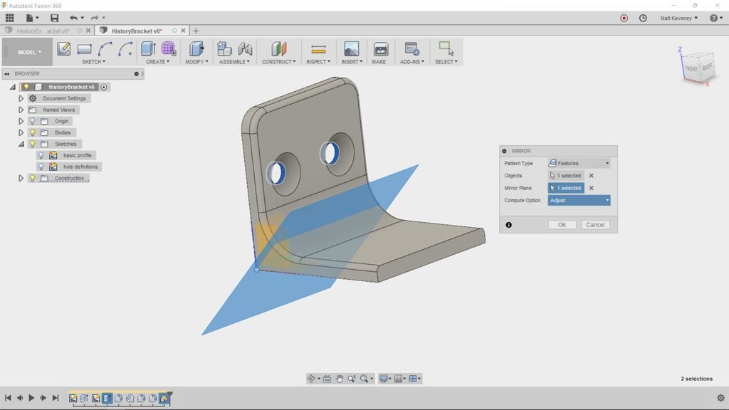
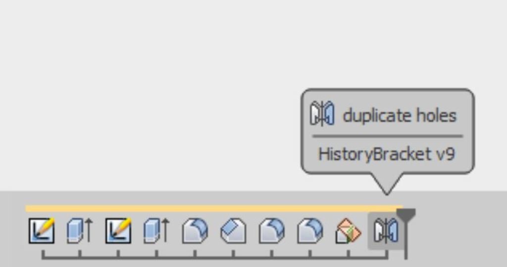
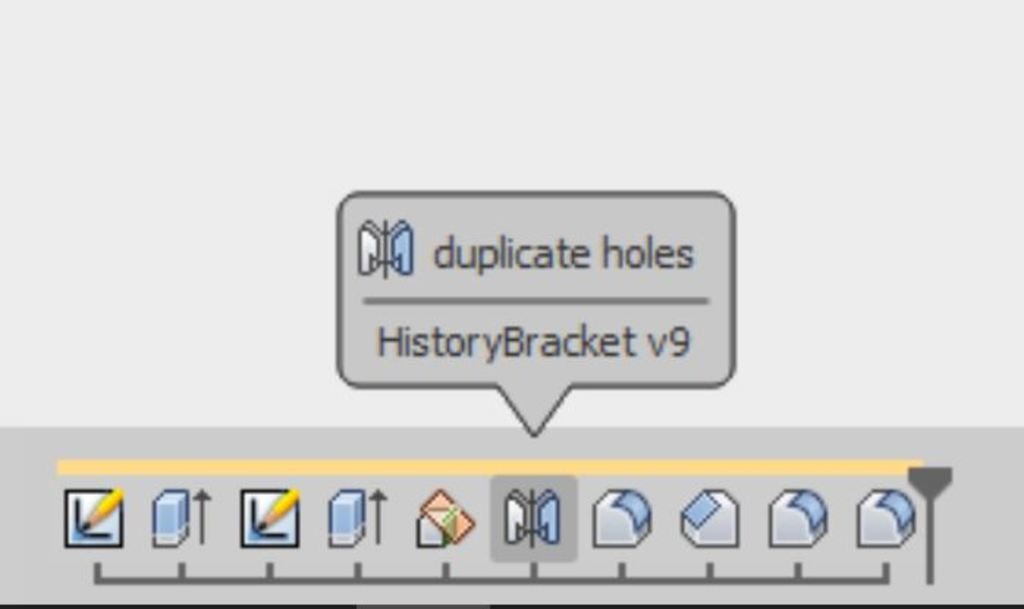
Right click the mirror feature and rename it duplicate holes.

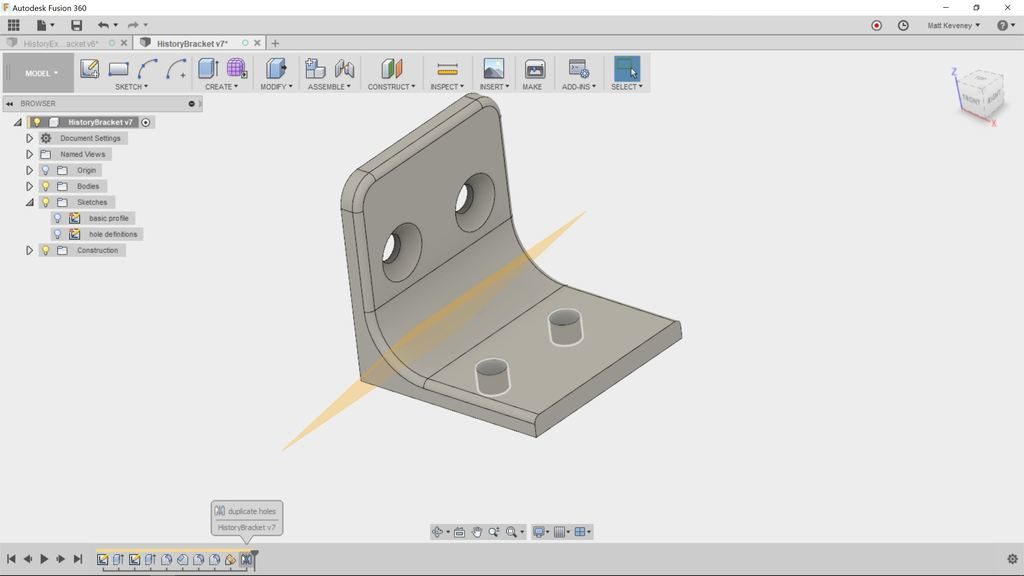
Turn the construction plane display off now, just for clarity.

We’d like to countersink these new holes too, but if you double-click to edit the countersinks feature, the new holes do not appear for selection!

That’s because the new holes did not exist at the time we created the countersink object. Note that the countersink feature appears before the mirror feature in the timeline. You might be tempted to simply add another countersink feature, but there’s a better way!

To fix, let’s move the reflecting plane and mirror objects to an earlier point in the timeline. Press shift and select both features. Then drag the features to the left. You’ll find you can’t go further left than our holes feature. Release the mouse button to complete the move.

This illustrates an important concept: Any feature that references another must appear after the dependent feature in the timeline. In this case, the duplicate holes mirror feature refers to the holes extrusion feature, so duplicate holes must appear later. This also applies to sketches that contain projected geometry: The edges being projected must be defined before the sketch.

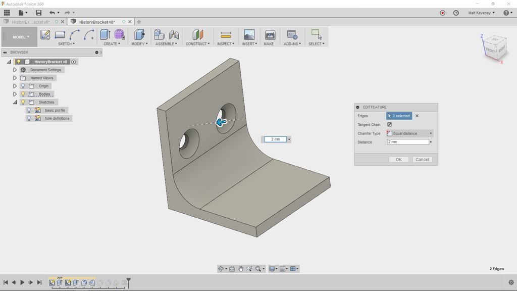
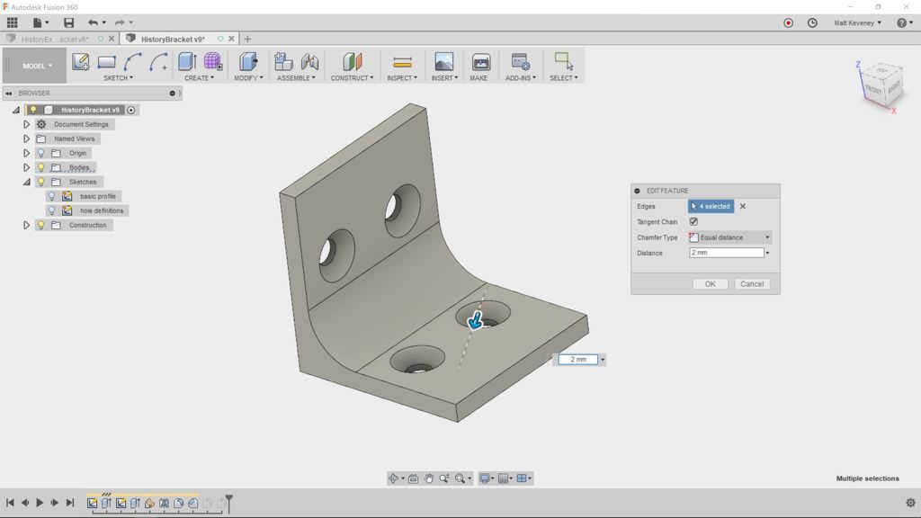
Now double-click the countersinks chamfer feature to edit it. Since it now happens after the mirror feature, we can add the new holes to the set of ‘edges’ this feature affects. Shift-select the additional holes and click OK.

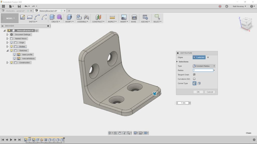
Let’s fix the corner round-over the same way. Double-click to edit, then shift-select to add the other two edges.

Finally let’s fix the break sharp edges feature again. Double-click to edit it. Click the ‘X’ next to the edges button do deselect all. Then reselect the edge. This time it should select the entire perimeter as originally intended.

Notice that we did all that cleanup without adding much to our history timeline. We removed one feature, then added two and adjusted a few.

The more natural thing might have been to add a new sketch and another extrusion for the extra holes; then apply the fillet and chamfer tools again. Resist this temptation! The model might look the same, but the document will be larger than necessary, will be more difficult to edit later, and will slow Fusion down.

With our concise model, edits are a breeze. Here’s the original plus 3 variants. Each variant was made by editing a single value in a single sketch or feature.


Remember: The history timeline is your document. The rest is just for show!


P.S. The document comparison I made here is oversimplified. Some bitmap editors like Microsoft Paint modify pixels directly, but Photoshop and Gimp documents contain layers and other high-level objects. A Blender document is actually a mixture of a mesh and high-level ‘modifier’ objects, among many other things. In Fusion 360, the ‘sculpt’ workspace offers freeform mesh-based editing much like Blender. Also, Fusion does store faces and bodies in the document that don’t appear as distinct items in the history. I simplified in order to illustrate my paradigm. I lied only to more clearly illuminate the truth.

The Vorpal Combat Hexapod

I demonstrated this fun robot at the last BoxBots build night and our general meeting last Thursday. Since then a few folks have asked questions so I thought I would post more detail.

The Vorpal Combat Hexapod is the subject of a Kickstarter campaign I discovered a few weeks ago. I was impressed and decided to back the project. I had a few questions so I contacted the designer, Steve Pendergrast. Then I had a few suggestions and before long we had a rich correspondence. I spent quite a bit more time than I’d expected to, offering thoughts for his wiki, design suggestions, etc.

Steve appreciated my feedback and offered to send me a completed robot if I would promise to demonstrate it for our membership. The robot you see in the photos was made by Steve, not me. Mine will be forthcoming!

You can read the official description on the Kickstarter page and project wiki. Here are my own thoughts and a few of the reasons I like the project so much.

It’s cool!

It has to be to get the kids interested; something that Ray has always understood with BoxBots. While BoxBots offers the thrill of destructive combat, the hexapod offers spidery, insect-ish, crawly coolness with interactive games and programming challenges.

It’s a fun toy

Straight away, this robot offers lot of play value. There are four walk modes, four dance modes, four fight modes, and a built-in record/playback function. To get them interested in the advanced possibilities, you have to get them hooked first. Don’t be intimidated by that array of buttons. At the Boxbots build night, the kids all picked it up very quickly. I couldn’t get the controller out of their hands.

It’s open-source

The circuitry, firmware, and plastic parts are already published. A lot of crowd-funded projects promise release only after funding, and some only publish the STL files, which can be very difficult to edit. Steve has provided the full CAD source (designed in OnShape).

Easy to Accessorize

The Joust and Capture-the-flag games use special accessories that fasten to a standard mount on the robot’s nose. This simplifies add-on design since there’s no need to modify the robot frame. There are also magnets around the perimeter, encouraging fun cosmetic add-ons like eyes and nametags.

Off-the-shelf electronic components

There are no custom circuit boards here. It’s built with two Arduino Nano boards, two Bluetooth boards, a servo controller, buzzer, pot, micro-SD adapter, two pushbutton boards, inexpensive servos, etc. This stuff is all available online if you want to source your own parts. If you’re an Arduino geek, it will all look familiar.

No Soldering!

I think every kid should learn how to use a soldering iron in school, but for some it remains an intimidating barrier. In the hexapod, everything’s connected with push-on jumper wires. (If you source your own parts you will probably have to solder the battery case and switches, since these seldom have matching connectors.)

Scratch programming interface

The controller and robot firmware is written in Arduino’s C-like language, but the robot also supports a beginner-friendly drag-and-drop programming interface built with MIT’s Scratch system. I confess, I haven’t investigated this feature yet, but I’ve been curious about drag-and-drop programming paradigms for years. My first programs were stored on punched cards. Finally, I have an opportunity to see how today’s cool kids learn programming!

It’s 3D printed

The parts print without support, and work fine at low-resolution. You’ll want to get your own spool of filament so you have the color available for replacement parts. Any of our printers will work. I’ve had good luck so far with PLA, but Steve recommends more flexible materials like PETG or ABS.

Anyway, enough gushing. I do not have any financial interest in the project. I just like to encourage a good idea when I see one. The Kickstarter campaign just reached its goal a few days ago, so it’s definitely going to be funded. If you’d like to back the Kickstarter or learn more, here’s the link. You’ll have to act fast; there are only a few days left. (Full disclosure: I do get referral perks if you use this link.) Remember that you always assume some risk with crowd-funding. I’ll make no guarantees, but I’m satisfied that Steve is serious about the project and is no scammer.

Click here for the Hexapod Kickstarter campaign.

If you’d like to see this robot in person, contact me on Slack. I’ll try to arrange a demo.

-Matt

Hands-on CNC class follow-up

We had a packed house for tonight’s Fusion 360 for CNC hands-on class.

Autodesk evangelist, Taylor Stein, walked us through Fusion 360’s workflow for creating the CNC setup and cutting paths. Then we adjourned to the big CNC machine and our own big-CNC steward, James, ran the job we’d just set up. There’s nothing quite so satisfying as seeing an idea become a physical thing.

The project was a fun beer caddy Taylor came up with. James and Taylor met earlier to test out the design; then did the final version with higher-quality material. A big thanks to James for making this happen. Contact James on Slack if you’d like to be certified on the big CNC machine.

We’re finding that folks really prefer this follow-along format. In earlier sessions we’ve used a question-and-answer approach in which Taylor demonstrates the solution while we all watch. While that’s often useful, we seem to retain a lot more when we actually press the buttons and drag the mouse with our own fingers.

So, next time we’ll repeat the hands-on Fusion 360 introductory class. This is an introduction to the modeling workspace, intended for first-time users. Bring your laptop with Fusion 360 already installed.

Click below to RSVP. The follow-along format slows things down a bit, so we have to limit attendance to a reasonable number; twenty is about all we have room for. If you want to come, sign up quickly; this is sure to be a popular class. If you find you can’t make it, please cancel so someone else can attend.

We’re always thinking about how we can improve these classes. If there’s a particular technique or feature you’d like to know more about, please let us know. Slack is the best way to make suggestions.

Hands-on Introduction to Fusion 360

Monday, Nov 6, 2017, 7:00 PM

Ace Monster Toys
6050 Lowell St #214 Oakland, CA

1 Makers Attending

Looking to get started with 3D modeling and Fusion 360? Join us for a hands-on introduction to Fusion 360 with Autodesk Technology Evangelist, Taylor Stein. This will be a follow-along class covering sketches, constraints, and basic 3D commands. Bring your laptop with Fusion 360 pre-installed (autodesk.com/fusion360 <">http://autodesk.com/fusion360…

Check out this Meetup →

3D Print Hangout, September 18, 2017

Wow, I’ve really slacked off on my hangout reports. This week we had three guests: Chelsea, Mack, and one other fellow who’s name I neglected to write down.

As we convened one of our 3D printing veterans, Brian, was just finishing up an incredibly cool model of Buzz Aldrin! This may be the biggest thing yet printed on our Prusa… over 6 hours at low-resolution! Inspirational to say the least. The designer (Brian’s friend) added a custom support structure platform that held Buzz upside-down while printing; the photos show it still attached.

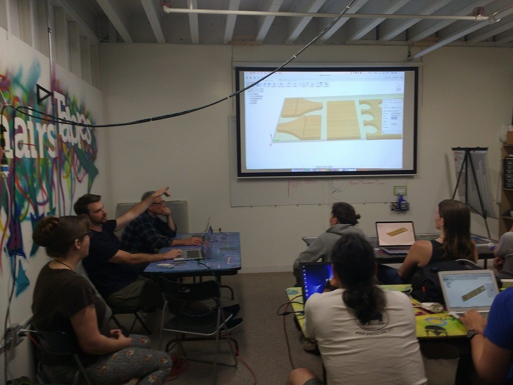
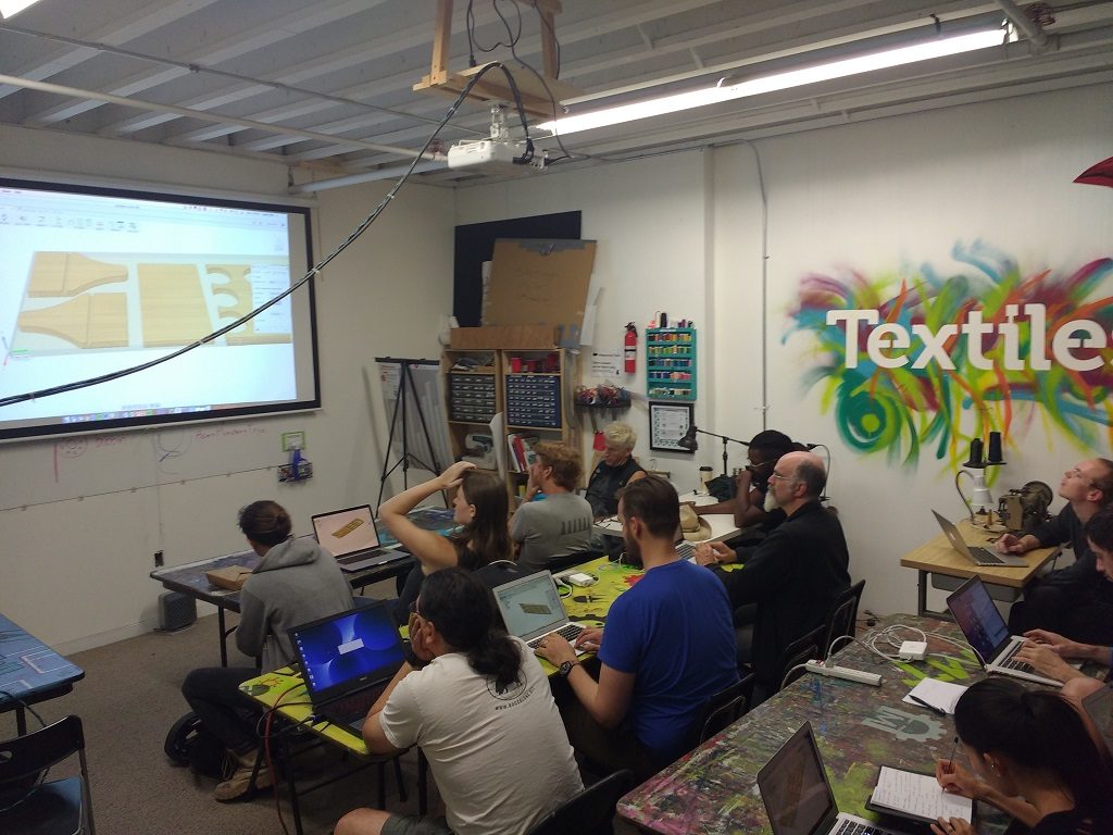
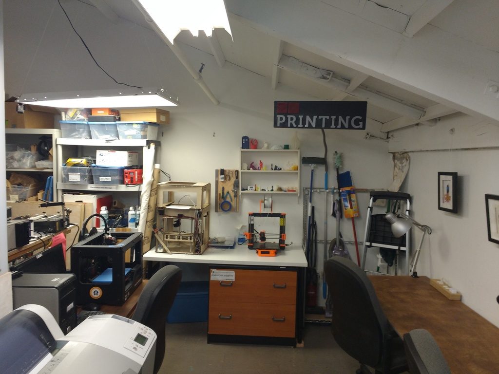
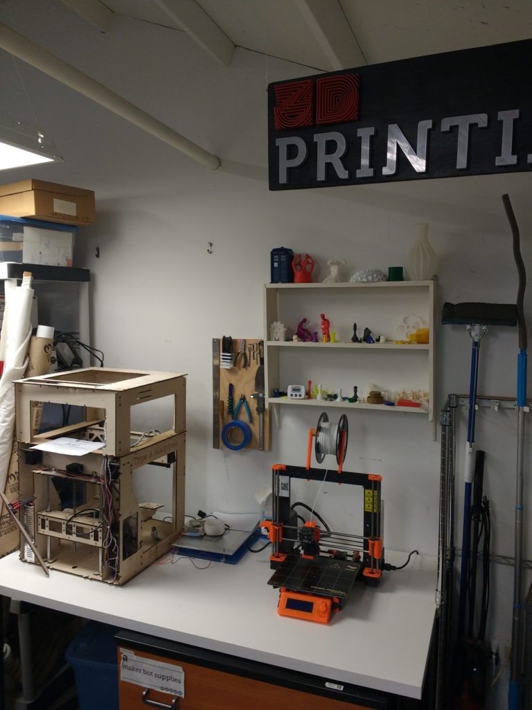
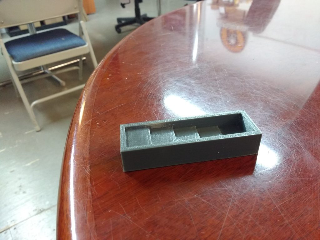
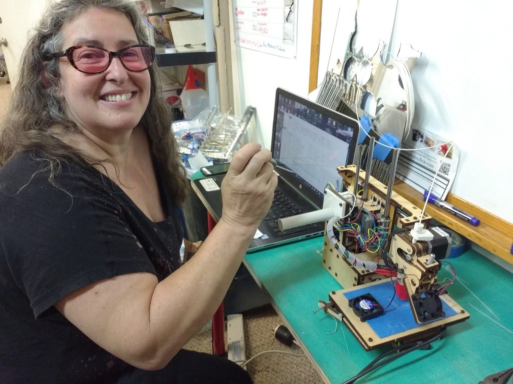
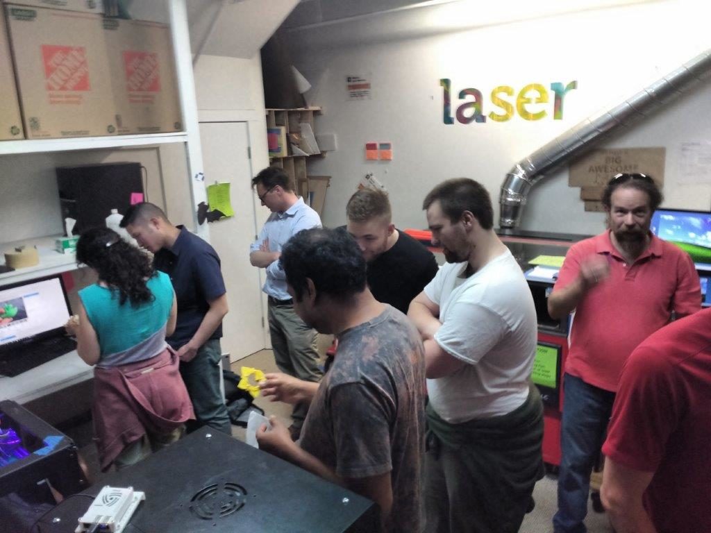
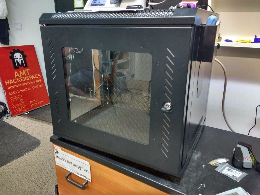
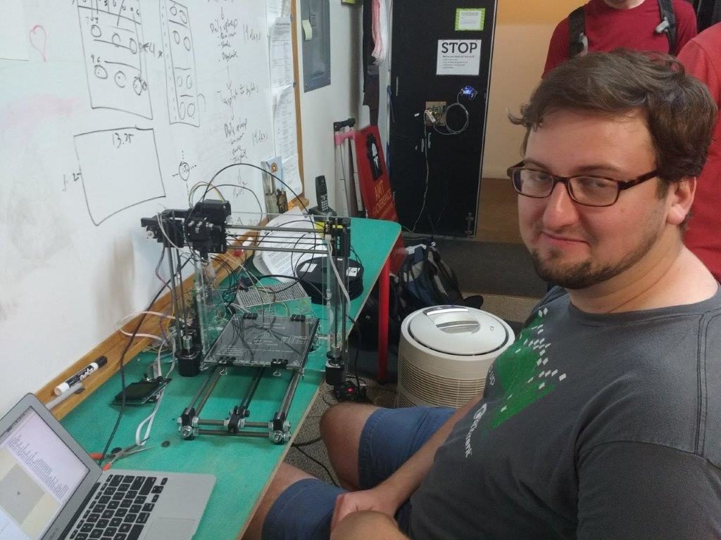
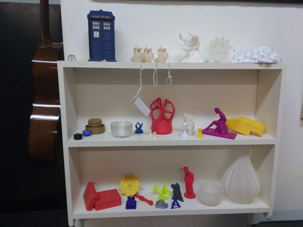
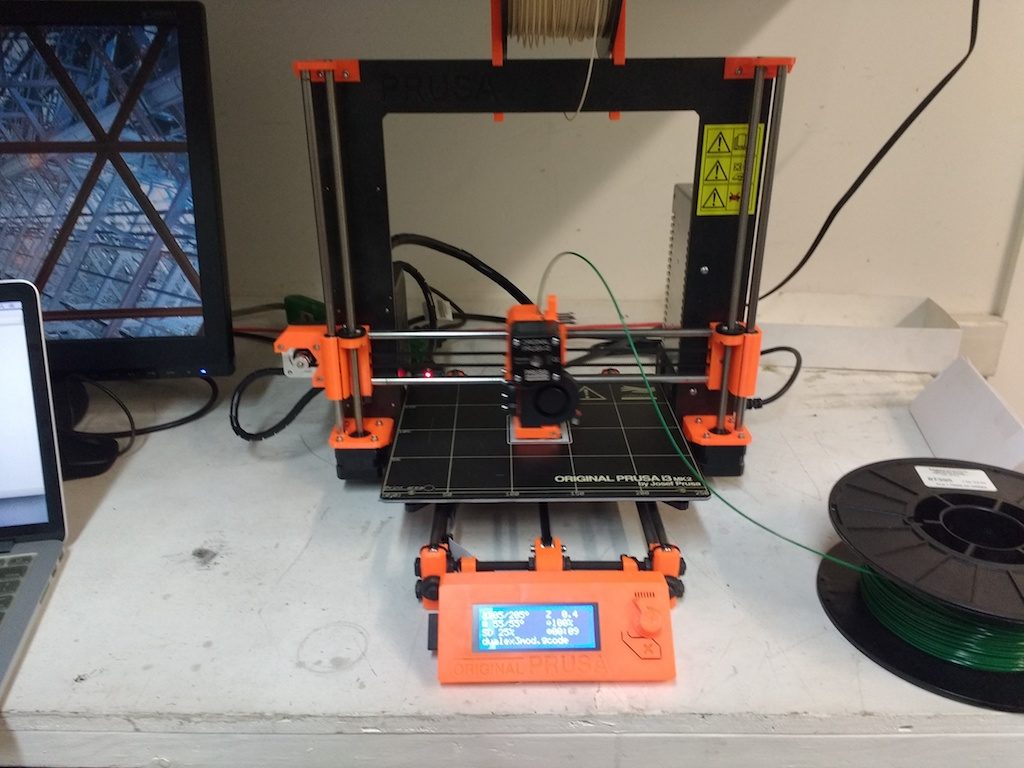
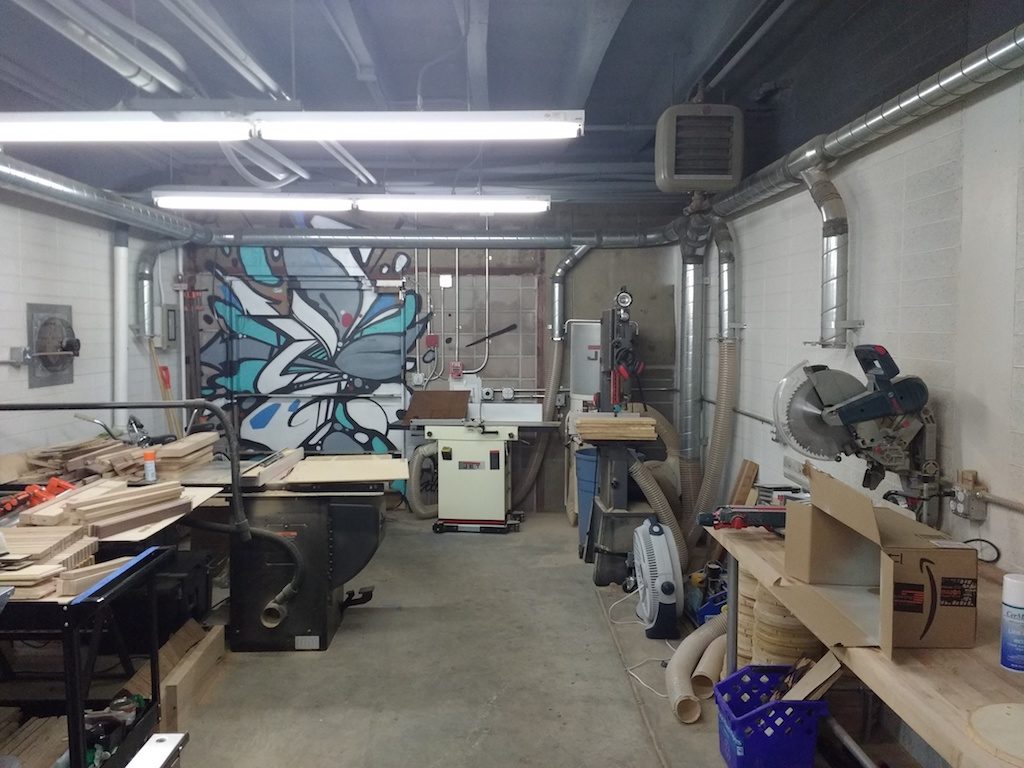
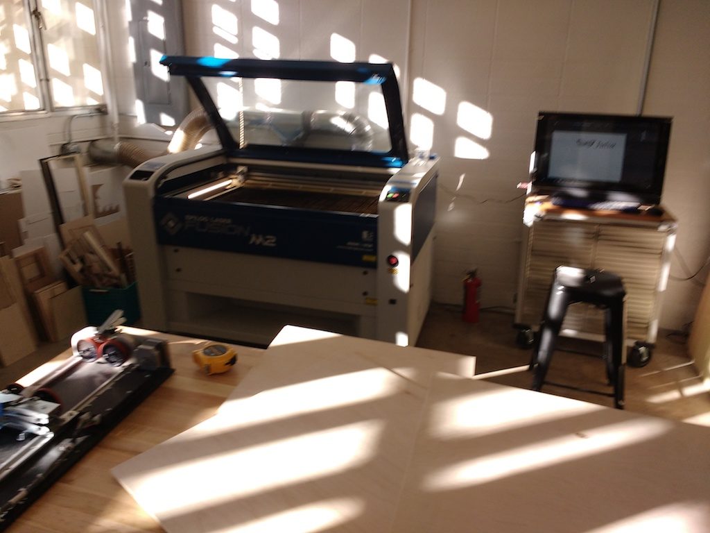
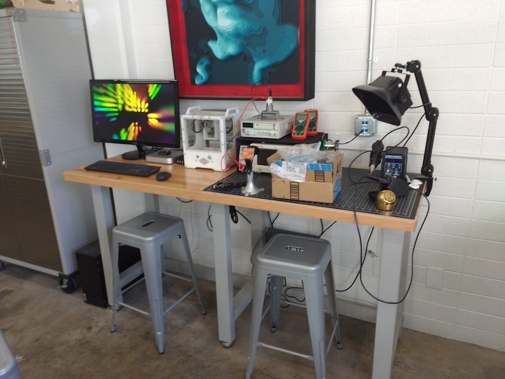
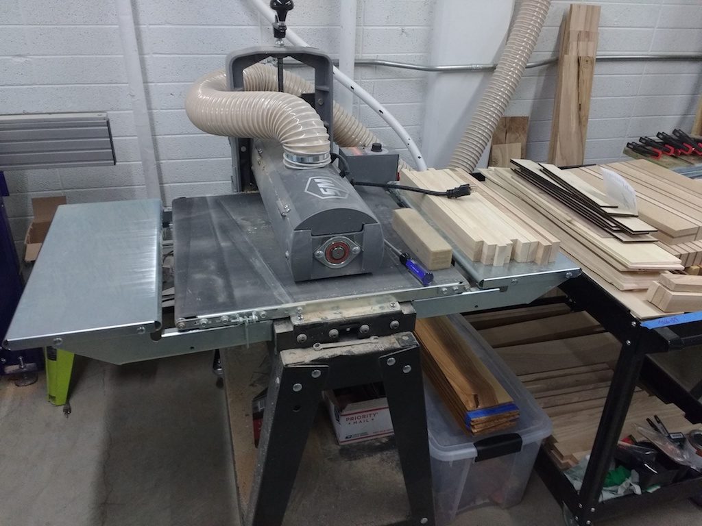
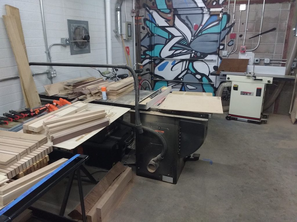
I’m still getting used to our new home, a cozy little corner upstairs in the northeast corner of the co-working space. I’ve found it easiest to conduct the classroom portion of the training at one of the big meeting tables. For the live-demo segment, we all squish back into the corner, or sometimes I bring a printer out to the big table. I haven’t figured it all out yet, so please have patience while I adjust!
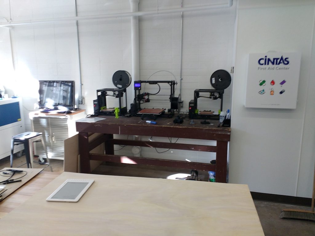
This week I demonstrated by printing a few parts Rachel commissioned for her electronic blinky stilt walker costumes. She needed a few small brackets to hold a fan and a power switch. These get sewn into the costume via the little mounting holes; you’ll have to ask her the rest of the details.

Chelsea has a few ideas for molding things in Silicone, but wasn’t sure how flexible the material would end up. So, we designed and printed a test mold of a small ‘staircase’ that exercises different thicknesses. We’ll have to encourage her to post the results!

Mack is a teacher, and had some cool devices his students use for momentum experiments. Parts like this can be difficult to model for 3D printing. Any support material would likely ruin the finish; but the curved shape can’t be printed without it.

We solved the problem by designing the spindle in three parts. The conical parts will be printed vertically, while the joining pin gets printed horizontally for strength. We didn’t get a chance to print this one; by then it was getting late out. This image shows the spindle only; the complete project includes a weighted disk in the middle, rather like a toy top with two points.

So that’s it for this time. Remember, we’re still doing the 3D printing hangout regularly, every other Monday. Check the calendar for exact dates, and come on by. You don’t have to be a member to attend. Experienced 3D print folks are especially encouraged to bring their cool items by for show-and-tell. We’d love to see what you can do!


3D print Hangout, July 10, 2017

We had another fun 3D print hangout last night.

Two newcomers and two veterans came, plus a few more who popped in later.

Just a reminder that we always start with 3D print 101, which takes about 45 minutes. The unstructured hang-out starts afterward. If you’re an experienced 3D-print veteran, it’s perfectly okay to skip the training and show up later. Bring your latest stuff; we’d all love to see it!

I brought my new rope-making gadget-set. I used ball thrust-bearings throughout, since I figured there would be a lot of friction once the rope strands were under tension. It was a great exercise in mating 3D printed parts to fit stock hardware–getting dimensions and clearances right is always a challenge.


I’m really happy with the result. It works great and makes a fun demo since it takes three people to use it. Nothing like having volunteers turn a crank and watch something new emerge before their eyes!

The big news of the night was Melissa’s new 3d printer! It’s an older laser-cut plywood PrintrBot simple she found online. It has a few miles on it to say the least; frankly I was not too optimistic. The gantry sagged, and I’d never worked with a ‘string drive’ before.

Still, all the electronics checked out; and the hot-end reached and held temperature just fine, so I set her to work tightening up and replacing a few dodgy-looking zip-ties.

That done, we configured Slic3r; leveled the bed and gave it a shot: The calibration cube printed just fine!

Even if it hadn’t worked out, an older project printer like this can sometimes still be a good deal for the components alone. The stepper motors seem to live forever, as do the electronics, linear bearings, etc. If you want a fun project; keep your eyes peeled for deals!

Don’t let inexperience be a barrier: I learned everything I know about it by surfing online. And of course, you can come to us if you need help.

Important note: our next hangout will be on Tuesday the 25th. That’s a day later than originally scheduled.


3D Print Hangout, May 1, 2017

Whew! it’s been a while since my last 3D print hangout write-up!  We continue to hold this event every two weeks.  We had a good turnout this week; about a dozen guests.
Terry brought along his Monoprice Mini that he got a few months ago for about $150.00.  It has  a small build area, but works right out of the box and has a large online community.
Terry also found a neat cabinet that the printer fits in perfectly.  It was originally designed for network appliances.  He lined it with foam for additional noise cancelling.
Will brought his nascent Prusa rework Reprap machine in for a bit of show-and-tell and tuning.  We got it going, and did some brainstorming for improvements.  Parts for this machine were made right here at AMT on our own 3D printers and Laser cutter.  Yes, you can make your own 3D printer!  If you’re interested, let us know.  We can even supply some of the parts from our stash.
 
Terry and a number of other members have expressed interest in deploying Octoprint for our printers.  Click out the link if you want to learn more about it.  We had a look at it and debated the pros and cons during this meeting.  I’m not entirely convinced it’s worth the effort, but Octoprint fans really love it.  I’d like to organize a task-team to set up a trial-deployment.  If you’re interested in participating, contact me on Slack!
 
Just a reminder, we now officially start the meeting with a 3D print 101 training session which takes about 45 minutes or so.  You may come later if you want to skip that part. Non members are always welcome.  Come join us!

Cool new sample shelf!

At last week’s Thursday gathering, I put out a general cry for help.  We needed a better way to show off the various 3D print samples we’ve accumulated over the years.

Devon was there and rose to the challenge.

If you are looking for a project to hone your maker skills, just talk to your friendly neighborhood steward.  I’m sure we all have a list of projects like this that will benefit the space.

Thanks Devon!

New 3D printer at Ace Monster Toys!

Over the last year it has become evident that our fleet of 3D printers is showing its age. First I upgraded the Type-A printer with a new hot-end and LCD/SD card reader.  It’s much improved, but still not reliably producing the quality I was hoping for. Meanwhile the Replicator 2 had an alarming number of maintenance issues.  Among other things I had to completely replace the hot end, and add a ‘bypass’ circuit to get the extruder fan running reliably. I’ve managed to keep both printers working (they’re still in good order as I write this), but my confidence in their long-term prospects is not high. Rachel suggested I look into a replacement.

So, a few months back, I made a list of criteria and started searching in earnest. I’d originally thought about building a machine from scratch, but ultimately decided on the “Original Prusa i3 MK2.” It ticked off most of the boxes on my list, and has received rave-reviews. Ours has been assembled, tested, calibrated, and deployed for use for about a week now.

Why this one?

So, why did I choose this printer? …particularly when inexpensive printer kits can be had for less than $200.00 these days?

Well, the inexpensive machines sold on AliExpress and elsewhere are great deals for individuals who don’t mind doing a bit of fiddling around. I still recommend them if you’re on a budget, and am more than happy to help if you need it.

Personally, I’ve always wanted to understand how things work, and have always preferred to build something myself rather than buy it. When I first joined AMT, I figured I’d be surrounded by like-minded folks.  We are hackers, right?  Those $200.00 printers are for hackers.

But, much to my surprise, most folks I’ve assisted here at AMT have no desire whatsoever to understand the inner workings or finer points of our 3D printers.  They just want to use the machine, with as little training as possible.  So, reliability and ease-of-use turn out to be all-important.

The Original Prusa i3 MK2 is about the least-expensive 3D printer that fits the bill. It’s a substantial improvement over the older i3 design that most of the clones are based on. (I really think he should have given it a newer, more distinctive name.) It features:

  • Automatic bed leveling! This addresses the number-one issue that plagues even experienced users here at AMT.
  • A special edition of the open-source Slic3r program, preconfigured for all common filament types.
  • A PEI bed surface for good adhesion and surface quality; no need for blue tape!
  • A special heated bed with varying trace density for even heat (an i3 MK2 exclusive, as of this writing).
  • Great documentation and support.
  • A genuine RAMBO electronics board.  This is probably the best 8-bit option available and features fuses on high-draw circuits.
  • A genuine E3D hot-end; not a cheap knockoff.
  • A machined aluminum frame with a rugged finish (many clones are acrylic).
  • High quality stepper motors, precisely matched to their function.
  • Precision lead-screws on Z-axis, integral to the stepper motors (no wobbly coupling nut).
  • Printed parts of the highest quality.
  • Well-thought-out wiring paths; no dangling cables.
  • Firmware that includes self tests, auto calibration, …even corrects for out-of-square assembly!
  • The entire design remains open-source in case replacement parts must be 3d printed. I damaged a minor part during initial assembly and was able to simply print another.

Besides all that, Josef Prusa has probably done more for open-source 3D printing technology than anyone. He and his company deserve our business.

Training now required

I host training sessions all the time, but we’ve never actually required training to use our 3D printers. They’re not all that difficult to use, and there’s little risk of hurting yourself.

But, during my tenure here (about a year now) I have run into a number of users who really should have had proper training. In some cases they risked damaging the machines. So I suggested that we tighten this policy up at a meeting a few months ago and got enthusiastic support. Starting now, training is required.

While the i3 MK2 is certainly the easiest of our printers to use, there are a few important things to know. Training only takes about 30 minutes or so, and will henceforth be the first thing we do at every 3D Print Hangout (every other Monday night). I’ll also schedule a few extra “training only” sessions so that everyone has a chance to attend. Training is free and open to non-members as well. If you can’t attend a regularly-scheduled training, get in touch and I’ll work something out.

I hope you have fun with the new machine! We’re getting great results so far!

Oh, by the way: This printer does not feature dual-extrusion, but there is a spiffy ColorPrint utility that allows you to pause the job at a specific layer and change filament. It works great and is lots of fun to use!  I used it for the AMT logo in the photos.  (The checkerboard used a related but experimental technique… watch for a future post on the subject!)


Visting Boulder’s “Building 61” Makerspace

I hope you all had a Happy Thanksgiving!

I’m in Boulder Colorado this week visiting family. On Friday afternoon I took some time out to visit the new Makerspace at the Boulder Public Library. It’s always interesting to see how other maker communities do things. I thought I’d share a few photos.

I barged in with no warning and introduced myself to Adam Watts, one of two library employees in charge of the space. The remainder of the staff are volunteers. Adam seemed happy to meet a kindred spirit and was kind enough to show me around.

There are three main rooms at Building 61; a small office-like room, a main workspace, and a (nascent) wood shop.

bms_map

I took no photos of the little office, but it’s a small room with a few standing-height desks and seems to be devoted to design work.

The main space has a work area in the center surrounded by specialized machines. They have three nice Lulzbot 3D printers.

bms_3d-printers

Next to them lives an Epilog 40 watt laser and its console computer.  Both LulzBot and Epilog are located in Colorado, not far away.  Adam says they like to deal locally when possible  … As do we!

bms_epilog-laser

On the opposite wall lives a new ceramics kiln; not quite operational yet.

bms_kiln

And, next to that, an electronics workstation, complete with a small CNC machine dedicated to circuit-board machining.

bms_electronics

The wood shop features a Table saw, chop saw, drill press, thickness sander, and jointer among other things.  The centerpiece is a brand new CNC router, about the same size as ours.  The wood shop is not quite up and running yet, but Adam says they’re getting close!

bms_shopbot bms_thickness-sander bms_table-saw

bms_chopsaw

The Makerspace is a relatively new offering at the library, made possible by a foundation grant. That explains where all those the shiny machines came from! They don’t have as much space as we do, but they seem to be making pretty effective use of the space they do have. Adam reports high public interest in all the programs offered so far.

Access to the space is free for everyone with a library card. Materials cost extra. Adam explained that he’d love to offer 24/7 access like we do, but that’s just not in the cards. The library requires them to have an employee present when the space is open, which is probably to be expected when dealing with a public entity. The offerings generally seem to be more structured as well: organized classes complemented by ‘drop in’ hours for various functions in the space.

But a lot of issues sounded very familiar: They’re figuring out how to set up the ceramics kiln without setting off the fire extinguishers; they had to cut a new hole in the wall for ventilation; … etc. I’m sure snags like this are common to every hacker space!

While I felt envious of all the spiffy new machines, I also felt proud of the volunteer spirit we foster at AMT. I think the energy we generate with our open-to-the-public classes and innovative programs like BoxBots makes up for a lot of grant money, and enables us to serve our community remarkably well. Of course, I don’t mean to suggest that we’d turn down your money, if you happen to be in a position to help!

Thanks Adam for taking the time, and best of luck with your new Makerspace! Boulder is lucky to have you!


Fusion 360 for laser cutting, follow-up

Just a few quick notes to follow-up my last post on Fusion 360 for laser cutting.

Inside-out

Recall that Ray noticed I had made no provision to cut holes in parts before cutting the part free. This can be done in the laser control software (Lasercut 5.3) by creating two layers. Select all the holes for the first layer; the part perimeters for the second layer. Both layers should be configured for cutting with the same power and speed settings.

I noticed that I seemed to be getting proper cut order nonetheless. I inquired about this on the Fusion 360 CAM forum. Sure enough, it turns out that Fusion 360 attempts to order the inner perimeters first by design.

You can manually override the cut order by checking ‘preserve order’ on the ‘passes’ tab of the contour operation (screenshot above). The cuts will then be performed in the order the contours were selected.

You could also create two contour operations, selecting the inside perimeters on the first one.  This essentially reproduces the above technique using Fusion 360 instead of Lasercut 5.3. I would prefer this method if I had to carefully control the cut order for a complex model; especially one that might change over time.

But for a complex project there can be a lot of paths to select. It’s a tedious step at best, even without this extra worry. My plan is to let Fusion 360 do its thing and double check with the ‘simulate’ function. So far it hasn’t let me down.

Don’t edit the DXF!

Note that Fusion’s control over the order of operations ends with the DXF file. If you edit the DXF later, by manipulating things within Lasercut or some other tool, all bets are off.

I generally do use Lasercut’s ‘unite lines’ tool before cutting, but this does not seem to affect the cut order. In fact, I’m not sure it’s really necessary. I haven’t tested without performing the ‘unite lines’ step.

Smoothing

I strongly recommend using the ‘smoothing’ feature, also located on the ‘passes’ tab. Without it, Fusion 360 will reduce everything to line segments, greatly expanding the size of the DXF. With smoothing on, ARC objects are emitted where appropriate. The simple example above (a rectangle with two circular holes), resulted in the following file sizes:

Smoothing on:   1166 bytes
Smoothing off: 22538 bytes

Hope that helps. If you want to try it out and need a hand, let me know!