Author: Matt Keveney

3D printing steward, CAD geek, software engineer, and technological history buff.

Designing a replacement tool grip in Fusion 360

This is what our filament nippers looked like in 3D printing.

The work fine, but one of the rubber grips has almost split in two.

A few weeks ago, Evan made a valiant effort at saving them:

But, alas, the patch quickly broke off.

It’s a great excuse for another Fusion 360 3D printing article!

I’ll make the replacement in PLA. It won’t be squishy like the original, but it’ll be more comfortable than the bare metal.

To model it, I took a photo; then used Fusion’s ‘attached canvas’ feature. The easy way to use this feature is to simply import the image, without entering any dimensions at all. Then, right click the attached-canvas object in the browser and select calibrate. Fusion will prompt you to select two points. I’ve chosen the little hole near the joint and the end of the tang, which measures 98.6mm

Now we can make a sketch of the profile. I fitted arcs to the shape as near as I can. I find this easier than using splines when the shape allows for it. I used the ‘Fix’ tool instead of dimensions, since the scaled photo is what really defines the size here. I did not bother modeling the business end of the tool.

Next I extruded this profile to a 2mm thickness.

This was done in a component called tang. Next I created a new component called grip and sketched the outer profile. I projected the tang outline first; then offset the lower and sketched the upper end to eyeball-match the existing grip.

This was extruded ‘downward’ to create the basic shape of the lower half of the grip.

Next, I sketched a profile and cut away a depression for the inner part. This profile was offset from the tang outline very slightly (0.2mm) to allow for a reasonable fit. In this case, I may have to adjust the dimensions for fit a few times anyway, so this step could probably be omitted.  Still, I think it’s good practice to explicitly design appropriate fit clearance for mating parts.

A chamfer on the bottom completes the grip. It’s not an exact match but it’s close enough.

Finally, I mirror the body to make the top half of the grip. I’ll print in two pieces and glue them together to avoid using support material.

When I don’t know for sure that I have the size of something right, I often print an ‘abbreviated’ version to test the fit. This part’s small enough that I probably don’t need to, but just to illustrate the step, here’s what I do. Use the box tool, with the intersect operation. Drag the box until it surrounds the area of interest. Precise dimensions are not necessary here; we’re just isolating the feature to be tested.

In this case, I’ve simply shaved off the bottom few millimeters. I can cancel the print after just a few layers and see how well it fits the handle.

Once I’m done testing, I can simply disable (or delete) the box feature in the history timeline.

Let’s print it and see what we’ve got!

Hm… not quite. The inner curve seems right, but the outer is too tight. I’ll tweak the first sketch and try again.

This one’s still not perfect, but I think it’s close enough. Here are the complete parts, fresh off the printer.

The fit is okay but there are a few minor issues: The parts warped very slightly when printed, and the cavity for the tang was just a hair too shallow.

A bit of glue and clamping would probably have solved the problem but I had to knock off for the day anyway, and took a bit of time the next day to reprint at my own shop. I even had some blue filament that’s a closer match to the original grip.

Here it is, glued and clamped up. I gave the mating faces a light sanding to help the glue stick better. I used thick, gel-style cyanoacrylate glue, which gives a few seconds to line things up before it grabs. It seems to work very well with PLA.

And here’s the result. Let’s hope it lasts longer than the original!

But wait… Has this all been worth it?

Well, probably not. I found brand-new nippers from a US vendor for $3.09 on eBay. They’re even cheaper if you order directly from the Far East.

Oh well.  I think the techniques are worthwhile to know. The main thing is that it made for a good blog post!


Four helpful projects you can do

I know what you’re thinking. I’m sure you think this all the time.

You’re thinking:

‘Gosh, I get so much out of Ace Monster Toys; I’d really love to give just a little back! After all, the membership agreement says I’m supposed to do one small thing a month, and one big thing a year. Boy, I don’t know though… what could a simple soul like me really accomplish?’

Then, you might think:

‘But, golly, I really don’t want to bother the officers or stewards with questions like this. They’re so busy already, I’d just be getting in their way.’

Have no fear! We’re never too busy to put you to work.

Here are a few ideas I’ve come up with in 3D printing. I’m sure any of the stewards will have other ideas if these don’t appeal.  The first three could be done while waiting for your next long print to finish!

Move the sign!

Now that we’ve stretched out along the west all, the sign is kind-of lost back there. Unscrew it and re-hang it. I’m thinking right over the Type-A printer would be a good place.

Wind some filament!

We have four loose spools of filament: two of natural PLA, one ‘wood fiber’, and another green ABS. Wind them onto spools so we can use them! You could do it by hand if you’re really bored, but I’d rig up a temporary axle with some clamps and sticks borrowed from the workshop. Something to do while waiting for your next long print!

Re-Hang Mario!

The Mario artwork is now hidden behind the Prusa. Move it up a few inches! That’ll require a hot glue gun and a bit of knot tying.

Make a new shelf!

Last year, Devon was good enough to build us this cool little shelf to hold 3D printing samples. Since then we moved upstairs and then rearranged again. But, now there’s no place to hang the shelf. (We’re not allowed to hang it on the nearby concrete wall.)

Instead, I’m thinking we ought to have a free-standing bookshelf-like-thing about the same size, to live atop the filament cabinet. Please talk to me before embarking on this one, so I know we’re on the same page! This would be a great candidate for your ‘one big thing’ for the year.

3D printed cabinet handles

My folks just moved here from out-of-state. Naturally a few things got broken in transit, including the cabinet door handles for a simple storage unit.

There was nothing appropriate in the right size at the local hardware stores. These have holes 5″ apart, which seems to be larger than average.

This is a great example of a simple and practical use of 3D printing. It didn’t take long to design or print, and looks great!

The originals were of circular section, which can be difficult to print. I designed a slightly different section that would print on its side without any support material. Note the use of a ‘driven’ dimension, just to manually ensure that the angle with the build surface will be at least 45°.

The body is generated with a single sweep operation.

The threads were too fine to print, so I modeled holes and tapped them afterward. Tapping plastic is a tedious process. You must withdraw the tap and clear the chips about every 3mm. While I’m always skeptical of plastic threads, these seem to be holding up quite well so far.

Further proof that 3D printing is not just for cereal box toys anymore!

Tool organizer in 3D printing

After the expansion, 3D printing ended up adjacent to a concrete wall that the landlord does not want us boring holes in. That means we can’t hang the tools up like I did before.

But I’ve always liked the desktop tool caddies that Ray made for electronics anyway. So, I knocked up a simple design and asked for volunteers to build it. Bob came through, and even finished it in a cool purple color, buffed to a nice shine. I almost hated to put screws in it!

But, last night, I finally got around to it. Thanks again Bob!

And yes, that’s a new caliper. Please leave it in 3D printing!

3D Printing with Spiral Vase Mode

In the last article, I shared a few photos of the numbered ‘billiard peas’ I recently made. Traditionally, these are selected from a pea bottle. This was a great opportunity to try the sample PETG material as well as the ‘spiral vase’ mode available in Slic3r.

When printing anything with a single-thickness wall, there is always a small flaw where the printer advances to the next layer. By default this point will land at nearly the same XY position, yielding an unsightly ‘scar’ running up the side of the piece. This scar is also a weak point of the print.

For this reason, most slicers feature a spiral mode. The printer moves continuously around the perimeter, advancing very slowly and evenly in the Z direction. This gives a superb, continuous surface finish.

When activating this mode, Slic3r PE automatically sets related settings accordingly; No top layer is allowed, perimeter thickness must be just one filament wide, etc. You can still control the with somewhat by adjusting the extrusion width in the ‘Advanced’ menu. I changed perimeters from .45 to .6 to get a slightly stronger bottle.

The model should be defined as a solid; otherwise Slic3r will try (and fail) to create both inside and outside surfaces. Model the outside dimensions only.

Since I wanted a stronger lip for my bottle, I designed a separate piece to be glued on later. I also made a snap-on cap, with a retaining ring, just to see how well this works with PETG.

I’m happy to say it worked perfectly on the first try. The PETG material is easy to work with on our Prusa, and noticeably more flexible than PLA when printing such a thin section.

Give it a try!

Adventures in Multi-Color 3D Printing

with just one extruder!

A couple weeks ago, Rachel asked me for a 3D printed AMT Robot similar to this one:

She wanted it to be done in our official logo colors, and was okay with a thinner version. This was a perfect opportunity to make good on my year-old promise to document my multi-color printing trick on the Prusa MK2.

Prusa-research offers a free utility which allows you to insert a filament-change-pause command at any layer in the print job. The new color will be used for the entire layer, until the next color change is encountered.


This can be useful for certain effects, like this little AMT robot plaque I made last year.

But true multi-color printing can be done the same way, if you have the patience to change filament manually at every color change. This eliminates the more complex multi-color models, but with a little planning, the filament changes can be kept to a minimum and yield surprisingly nice effects!

The basic steps are:

  • Prepare your model
  • Configure the slicer for multiple-extruders
  • Load the STLs and slice
  • manually edit the gcode, replacing extruder changes with filament-change-pause commands
  • print as usual; change filament when prompted

These instructions assume Slic3r and our Prusa i3 MK2. Your printer must support a working filament change pause command. Unfortunately, this command is not universally implemented. If you’re unsure, you might want to try a small-scale experiment or two.

Prepare the model

I made a new model in Fusion 360. There are three colors: Black, white, and orange. I modeled the different colored sections as separate bodies like so:

Note that there’s a white section just behind the orange eyes. That’s because the orange I have available is a translucent color which did not show well when printed over the black main color.

By changing visibility and exporting the model three times, I ended up with one STL for each color, even though the white and orange sections have multiple bodies.

Configure the slicer

Note: Please don’t save these configuration changes on our 3D print computer. Make temporary changes only, or use your own laptop.

Under printer settings/general, set extruders to 3 (for three colors). The additional extruders will be copies of the first, which is what we want.

Choose extruder 1 and scroll to the bottom of the panel on the right. Click the ‘extruder color’ settings and choose black. Set Extruder 2 to white and extruder 3 to orange.

Slice the model

Click ‘add’ and load the main (black) STL file. Then click ‘Settings’ and use the ‘load part’ command to load the white and orange STL files.

Select each part in turn and choose the appropriate extruder: For the main black part, use extruder 1; for White use extruder 2; for Orange, extruder 3.

Adjust the rest of the settings as desired. I’m using default settings for the .020mm Normal profile.

Click ‘Slice now’ if necessary, and choose ‘preview’ on the ‘plater’ tab. Check ‘tool’ to activate the tool-specific preview colors. Your preview should look like this:

Export to gcode and save to a local file.

Edit the gcode

Open the .gcode file with a text editor and find all the lines containing t0, t1, and t2. These ‘tool change’ commands correspond to extruders 1, 2, and 3 respectively. A few of them will appear in a ‘preamble’ near the beginning of the file. In the body of the file a Tx command appears for each nozzle change. The idea is to delete the ones that don’t matter, and replace the rest with M600 commands. Your slicer may give slightly different results than shown here, so a basic understanding of gcode is assumed.

In my case the first was a lone T0 command that selects the first extruder to use. I left this one intact.

.
 .
 .
 G90 ; use absolute coordinates
 M83 ; use relative distances for extrusion
 T0  ; leave this one alone!
 ;BEFORE_LAYER_CHANGE
 ;0.2
 .
 .
 .

Slightly further down, three M104 commands appeared for setting nozzle temperature. I deleted the t1 and t2 versions.

.
 .
 .
 ;AFTER_LAYER_CHANGE
 ;0.4
 M104 S210 T0 ; set temperature
 M104 S210 T1 ; set temperature ; delete these
 M104 S210 T2 ; set temperature ; two lines
 G1 X116.894 Y125.880 F7200.000
 .
 .
 .

Then the actual printing starts using the T0 (black) nozzle already selected. The next one encountered is T1.

.
 .
 .
 G1 E-0.15000 F2100.00000
 G1 Z1.400 F7200.000
 T1  ; change to M600
 G1 E-0.80000 F2100.00000
 G1 X128.346 Y108.791 F7200.000
 .
 .
 .

Change this and all remaining Tx commands to M600. While you’re at it, make a list of which extruder numbers were selected. Check them off as you go, so you know you’re loading the correct color. In my case, this list looked like this:

0 -start with black-
 1 white
 0 black
 2 orange
 0 black
 2 orange
 0 black
 1 white
 0 black
 1 white
 0 black ..for remainder of job

Print

At each M600 command, the printer will pause, prompting you to load the next color.

Results? Hm…

My results with the robot were a bit disappointing. Since these colors are very high contrast (black and white) the slightest little blob will noticeably mar the finish.

Also, I learned that translucent colors over a black layer need a lot of layers, or a white layer or two behind them to keep them from looking too dark. I was not satisfied with the eyes in any of these models.

One last issue is that the Prusa seems to extrude a bit of extra plastic just after resuming the print, but before the nozzle gets into position. This almost guarantees the aforementioned ‘blob’ of plastic, which invariably lands in the wrong place. With a bit of practice, I was able to quickly grab this extra blob with tweezers, but clearly there’s room for improvement! Maybe there’s a setting I missed somewhere.

Still, I think it’s a worthwhile technique to know, especially if combined with other effects.

I’m an avid pool player and have recently taken an interest in games that require each player to randomly choose a ‘game ball.’ The traditional way to do this is via a set of ‘peas’ and a shaker bottle.

My peas are spheres with a flat spot on on side; the flat part faces down when printing. The numbers are recessed into this surface. These might work fine as-is, or a bit of paint could carefully be applied in the recess. I decided to try embedding a disc of contrasting color just behind the recess. I printed in white with green highlight, and got good results by turning the speed down to just 40% for the first few layers. Those finely detailed numbers are tricky! (I’ll save the bottle for another post!)

Fusion 360 Hangout Notes

We had a great session last night (2-12-18) at the Fusion 360 hangout.

  • I burned most of the time presenting the design discussed in my recent blog post on best practices. I fielded lots of questions and expanded on some of the points in that post, so everyone seemed to get something out of it.
  • Chris has been struggling with sketches that began life as imported DXF files. Lots of funny duplicated lines in the skeches we looked at. We kicked around a few ideas for him to try, but nobody had the magic answers.
  • Steve has been playing with Fusion’s Drawing feature & had some neat things to show.
  • Bob showed us some of his progress carving Guitar parts. This is complex CAM stuff involving multiple operations and remounting parts to carve two sides. Can’t wait to see the progress.

A ‘pair-programming-style’ hangout was proposed for a future session. I think it’s a GREAT idea… We work together in pairs, sharing experience and generally bouncing ideas off each other while working through real member projects.

This kind of meeting can be run by anyone… and I’m looking for volunteers. I think a group meeting would be a lot of fun… that way we could negotiate which projects we might be able to help most with, or are most interested in. …but it doesn’t _have_ to be a group meeting. If nothing else, feel free to pipe-up in this forum anytime you get stuck and think an extra set of eyes would help. And _do_ make yourself available to others: I’ve learned a great deal about Fusion through other folks’ projects, since they so often approach the tasks in a way that would never occur to me.

By popular request, I’m going to put together a more traditional class for next time, focusing on beginners. The hands-on format was overwhelmingly preferred to anything else we’ve tried, so we’ll go with that. No schedule yet; watch this space!

Best Practices for parametric design in Fusion 360

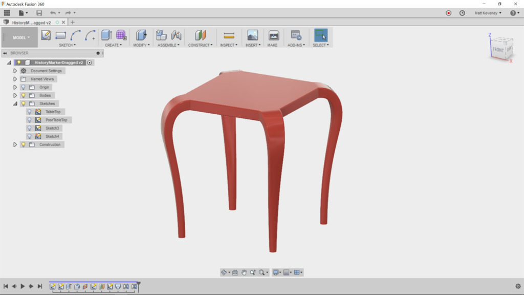
On Monday, Chelsea came to me with a question about Fusion 360’s loft tool. I was unable to give a quick answer, so later I practiced a bit by making an approximate copy of the design she was working on. As I was looking it over, I found that it also illustrated a few ‘best practices’ I’ve cultivated that I think make my designs easier to edit and maintain. Chelsea has given me permission to share them with you here.

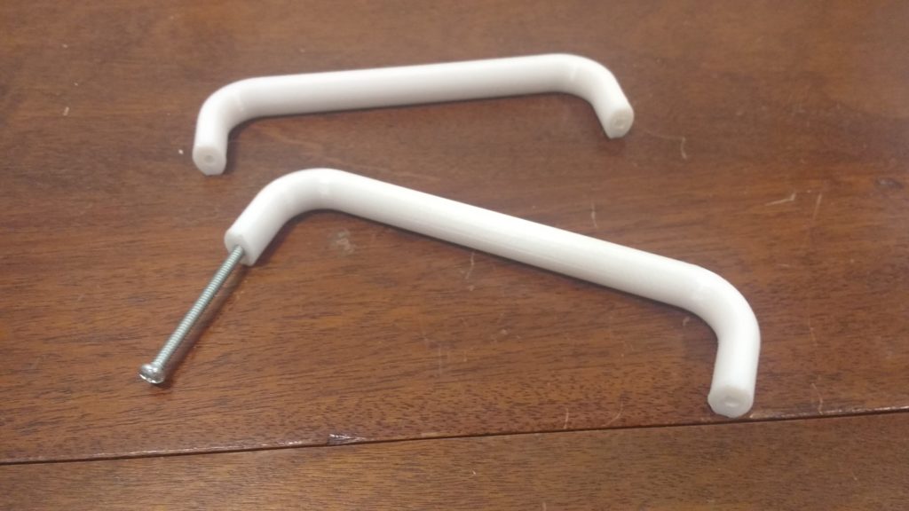
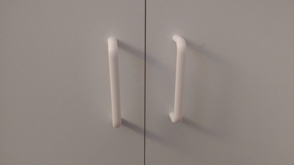
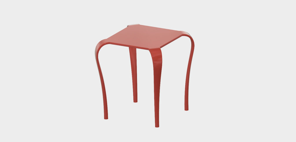
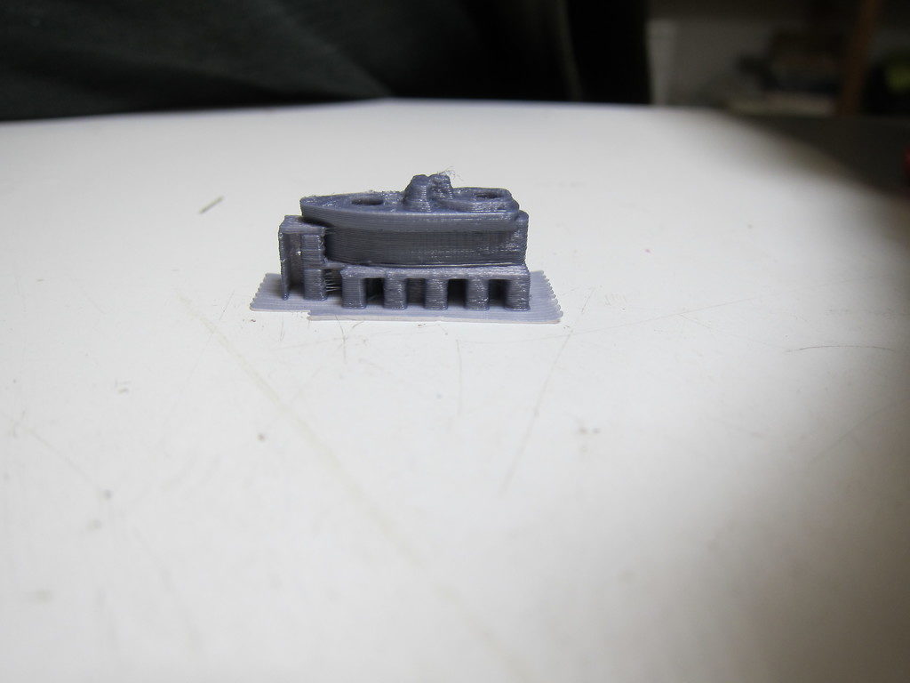
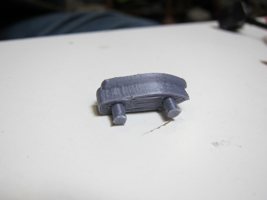
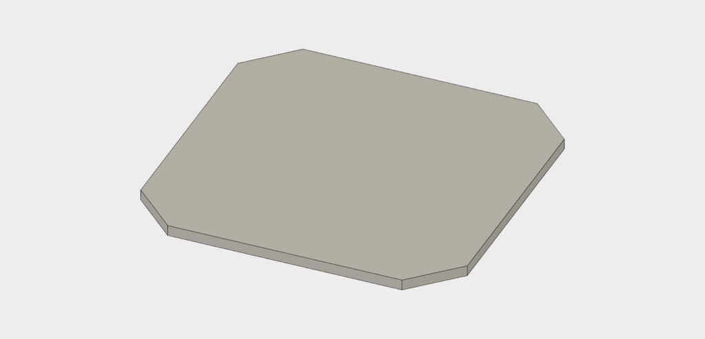
The project is an end table with legs that gracefully descend from a simple square top. The legs emerge from the corners of the table, bend downward, and transition to a circular section at the feet. Imagine four angry Cobras swallowing the corners of the tabletop!

The legs look like a job for Fusion 360’s Loft tool. Since this loft must follow a curved path, we’ll need either centerline or guide rails, and a bit of planning to make it come out right.

Here are the steps I took. You may follow along and recreate it, or merely inspect my design linked below. This is not a tutorial for complete newcomers: I gloss over the keystrokes and mundane details. I think it will be worthwhile reading anyway. The sooner you adopt habits like these, the faster you’ll become productive with Fusion.

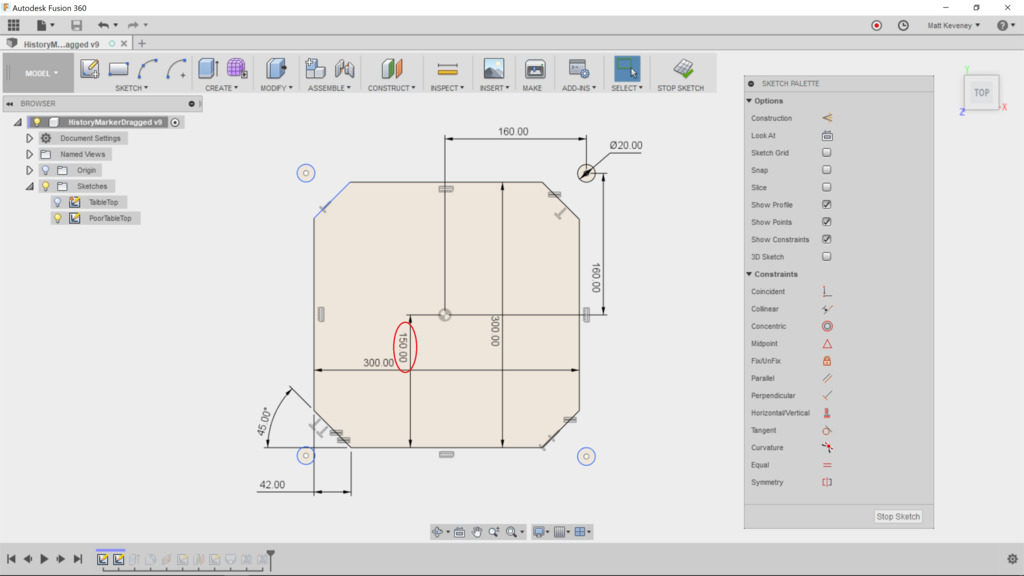
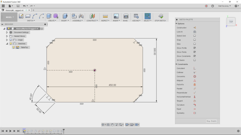
First sketch the tabletop on the horizontal plane which is X/Y in my configuration. Note that I’ve deliberately put the sketch origin in the middle of the tabletop. Since this tabletop is symmetrical about its center, this may come in handy later.

Note also that I’ve managed to fully constrain the sketch using just two dimensions (and a lot of other constraints). I’ve chosen dimensions that define the features that I may want to alter later: the overall width of the tabletop and the width of the corner faces.

Keep your sketches tidy!

When helping folks out with Fusion, I see a lot of messy sketches. I think the best sketches have no more detail than needed to support their associated operation, are fully constrained, and clearly express the design intent.

Above all, do get in the habit of fully constraining your sketch every time you edit. You should not be able to drag a line or curve out of place.

This is especially important in Fusion 360, since it’s possible to jog sketch elements around without first opening the sketch for edit. When selecting an unconstrained profile to be extruded or revolved, it’s way too easy to bump something out of its intended location. I think this is a terrible feature of Fusion, but if it disciplines you to constrain your sketches, perhaps it’s ultimately a good thing!

Here are a few other things I try to avoid:

Duplicated dimensions

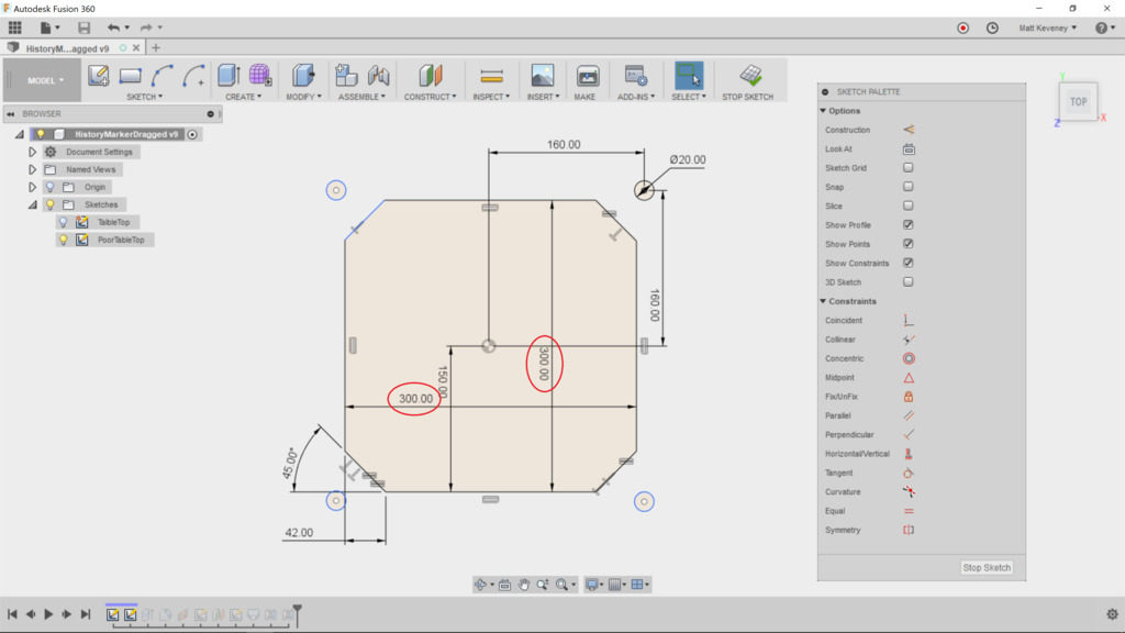
If two features are the same length, use the equal constraint instead, or at least reference one master dimension from the duplicate. This way, you’ll be able to change the dimension in one place.

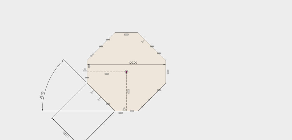
Dimensions on the wrong things

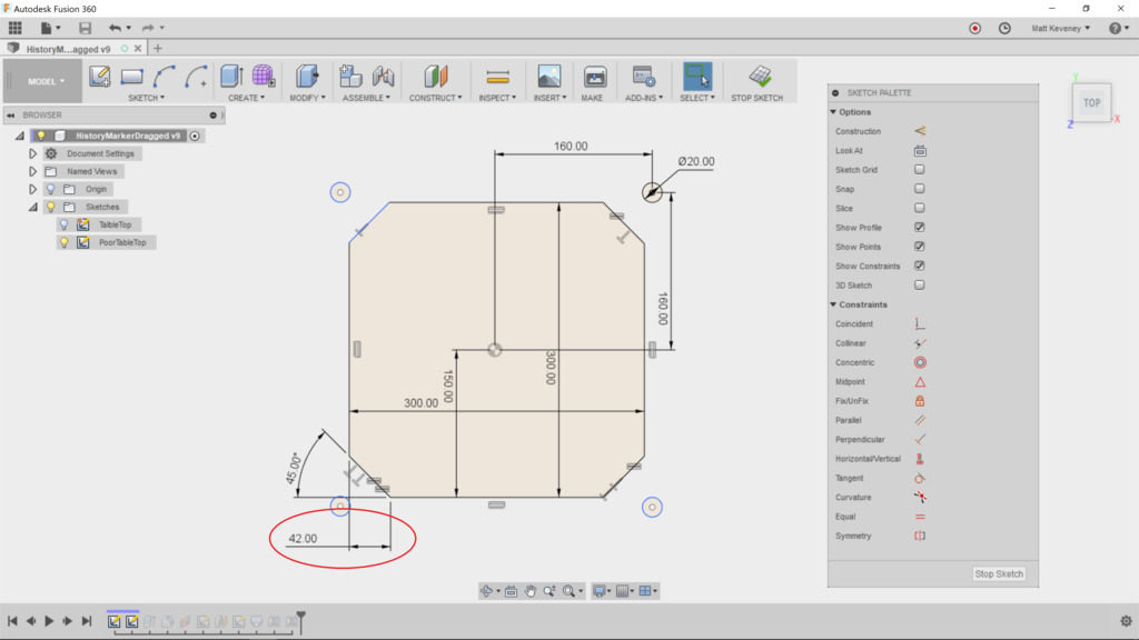
The corner edge could be constrained by defining a distance from the cutoff corner, but this does not seem like the most natural choice. If I were describing this table to a friend or client, I would rather say “the legs are 60mm wide at the top” than “the legs descend from edges that were cut 42mm from the corners.” This is my guiding principle when choosing which features to dimension: Would I describe it to someone else in the same terms?

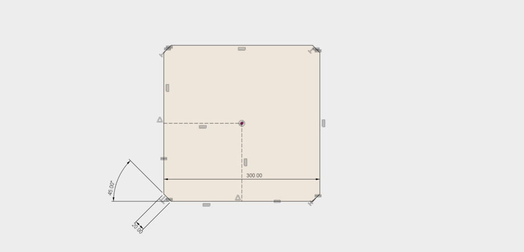
A dimension where a constraint is more appropriate

Here the top has been centered by specifying dimensions one half the width of the tabletop. Using a pair of construction lines constrained to the midpoints clarifies the intent, and eliminates a step if we ever want to resize the table.

Unconstrained geometry

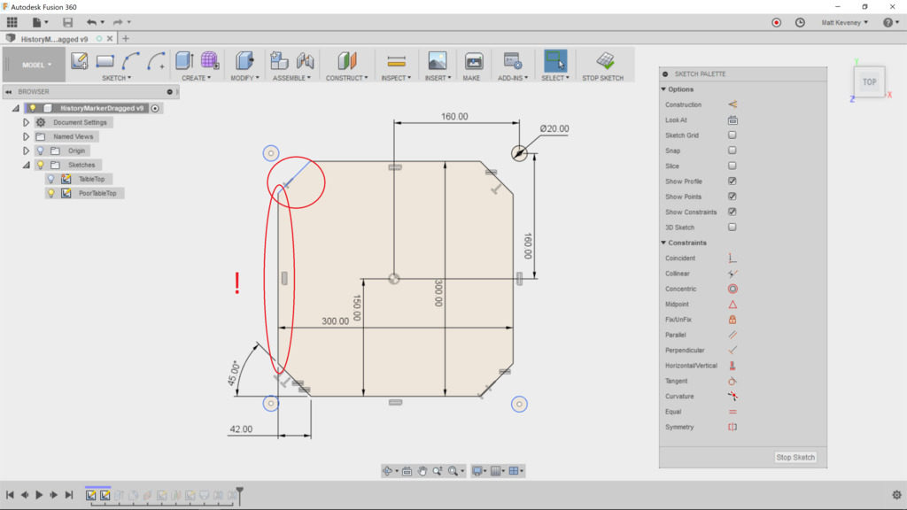
A few of the edges appear to be correct, but have not been defined. It may look okay on screen, but if you render this design with a CNC machine or 3D printer, the part dimensions will be incorrect.

If you’re transitioning from an older CAD or illustration program that relies on a ‘snap grid’ to align points, break that habit now! The grid may be convenient for drawing something in approximately the right size, but it does not constrain your sketch geometry. I recommend you turn the grid off and never look back.

Note: Fusion tries to display unconstrained geometry in blue, and constrained geometry in black. Unfortunately this feature is riddled with bugs! I’ve seen countless cases where partially constrained geometry is displayed in black, like the left vertical edge of this sketch. Beware!

Superfluous geometry

The profiles of the feet have been defined in this sketch as well, even though those profiles will not be used when extruding the tabletop. I see this a lot. The designer may be thinking in terms of old-fashioned blueprints, which were intended to communicate a design. A top-view drawing of this table would generally illustrate the position of the feet, and would probably show the shape of the legs from that perspective too.

Sketches in Fusion are for defining the design, not for communicating it. Each of these features should be defined in a separate sketch. If you need a drawing, create it with the ‘drawing’ feature after the model is complete.

Just before closing any sketch, always try modifying a dimension or two, just to make sure the sketch resizes as you expect:


Now back to the model. Save the sketch and extrude the tabletop. I’ve chosen a thickness of 10mm.

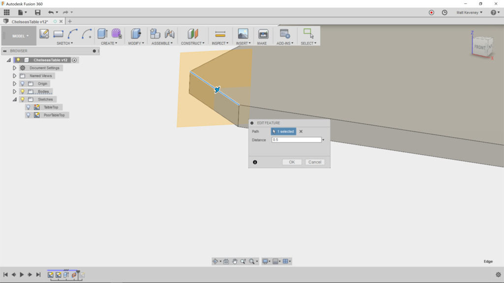
Now we need to create a construction plane on which we’ll sketch a loft center-line. We have a lot of choices here: we could use the ‘Midplane’ tool, choosing two opposite corner faces, or we could use the ‘Plane at Angle’ tool, using the central vertical axis and an angle of 45 degrees.

In this case, I prefer the ‘Plane Along Path’ tool, selecting the upper edge of one corner as the path. The distance must be set to 0.5 to position the plane in the middle of this edge. Since it’s defined relative to this line only, the plane will remain in the correct place even if we decide to make the tabletop rectangular instead of square.

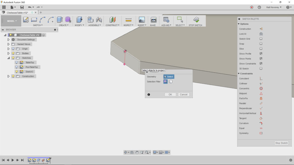
Create the sketch on this plane and project the corner edge of the table that we’ll be lofting from. This is the only projected feature we need, so I like to hide all the bodies at this point. I also hide all other sketches. This prevents inadvertent projection of other edges we don’t need to reference, and makes it clear which lines/features are actually in the sketch we’re editing.

I think Fusion’s auto-projection features can do more harm than good, especially for newcomers. If you’re not careful they will add extraneous and confusing cruft to your sketches. Do your sketches contain lots of purple lines and points that seemed to spring from nowhere? Consider turning these two features OFF, at least for a while:

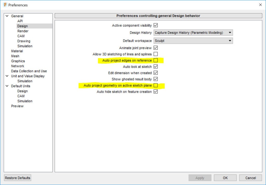
With these disabled, you’ll have to explicitly use the ‘project’ command to project an external edge into your sketch, so you’ll always know when it happens. Once you get the hang of it, you may want to turn these time-savers back on, though I’ve never liked the second one. I think it adds way too much unnecessary guff to my sketches.

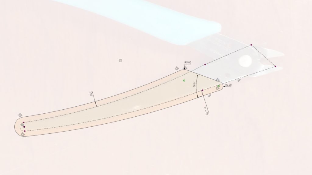
Now on with the sketch. First of all, I like to convert the projected line to a construction line, since it doesn’t really participate in defining the new profile or path I’m creating; it merely serves as an anchor to keep the new geometry in the correct relative position. Create the center line as a spline through just three points.

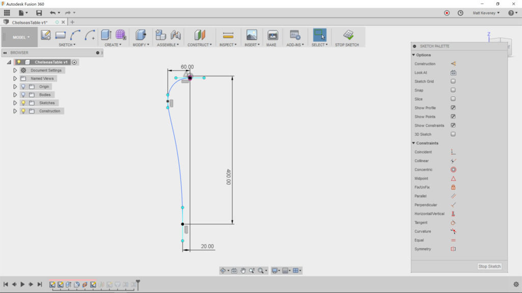
Note that I’ve constrained some aspects of the spline but not all–a rare case in which I intentionally choose not to constrain everything.

  • The position of the foot of the leg is defined in relation to the corner edge of the table.
  • The upper end of the spline is attached to the midpoint of the projected edge, since we want it to spring from the middle of that profile.
  • A horizontal/vertical constraint is applied to the upper endpoint’s ‘control handles,’ so the the end of the curve will be perpendicular to the existing face. Another at the bottom makes the leg end perpendicular to the floor.
  • The middle control point’s horizontal distance from the table edge is defined so that this distance is maintained even if we change the size of the table. By fixing this control edge vertical, we ensure that this dimension defines the outermost edge of the curve.

I like to leave the remaining aspects of the spline fluid. This shape seems to be an organic element the designer creates by eye. We could use the ‘fix’ tool to constrain the curve once we have it right–something I would generally advise. In Fusion, doing so interferes with resizing the tabletop, so I like to leave it fluid.

Note: What I really want here is some kind of ‘relative fix’ tool that locks the curve in relation to a specified sketch point, but Fusion doesn’t seem to have any such thing. Fusion’s ‘fix’ tool fixes the curve in absolute 3D space, which is admittedly easier to understand.

Now we need a sketch defining the bottom profile of the leg. Since we have no existing face there, we first create a construction plane.

But let’s think about this a minute! This plane should always be the same distance from the tabletop as the corresponding dimension in the centerline sketch. We can achieve that by defining a parameter and using it in both places.

Create a parameter called ‘TableHeight’ and set it to 400mm.

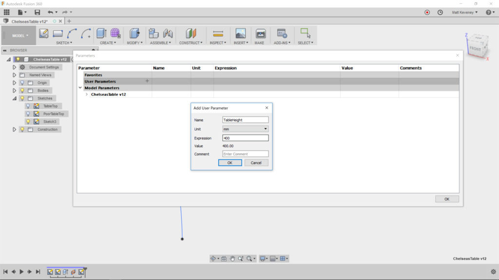
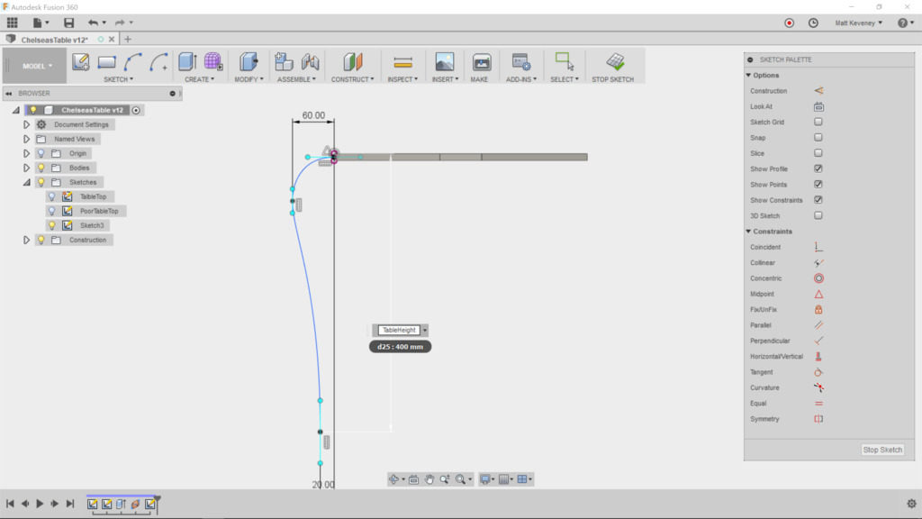
Then edit the centerline sketch and change the height dimension to ‘TableHeight.’

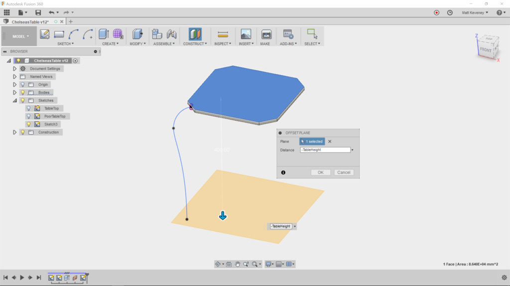
Now, finally, create the offset plane, referencing the top surface of the table, since that’s the point we measured from in the sketch. Set the offset to ‘TableHeight.’

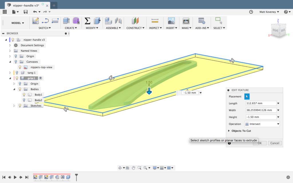
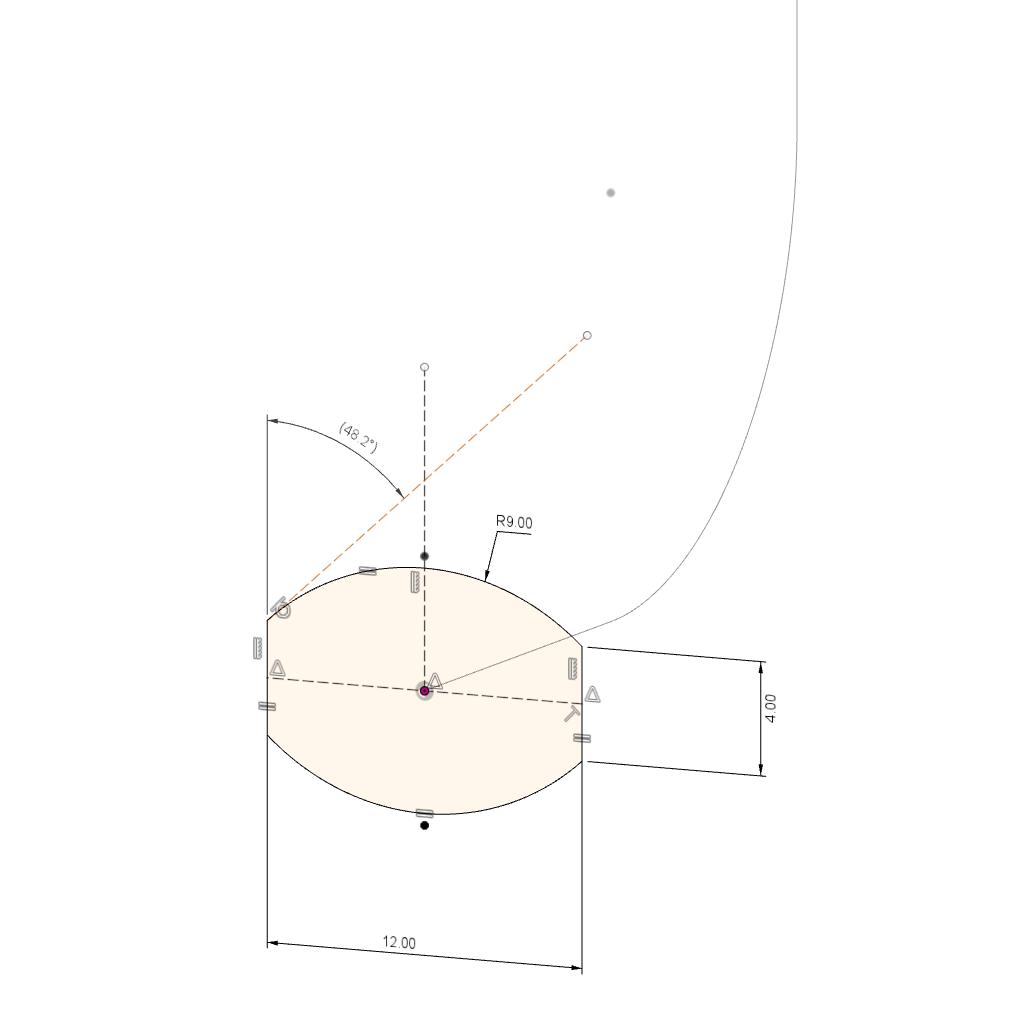
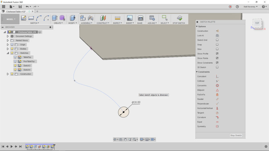
Now create a sketch on this new plane. With the centerline sketch visible, project the lower point of the centerline into our sketch. Hide the centerline sketch now, so it doesn’t distract us. I’ve chosen to just create a circle centered at the projected point and dimensioned to 20mm. Whatever shape you choose, it should be centered on this point, since the centerline is expected to pierce the center of the loft profiles.

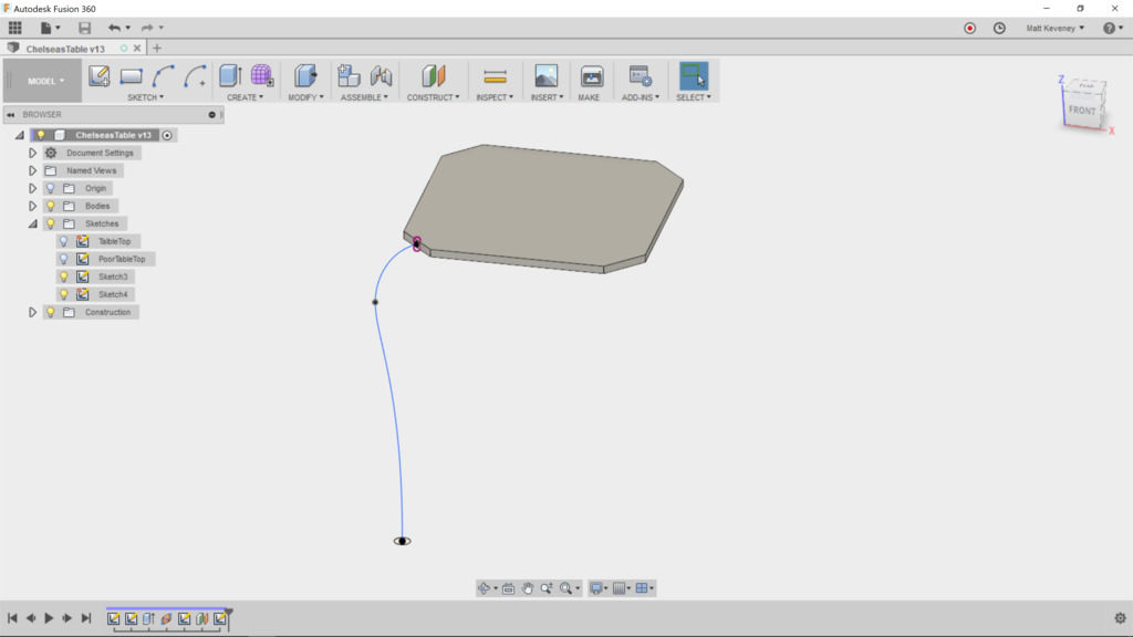
Finish the sketch, and turn on visibility of the centerline sketch and the bodies again.

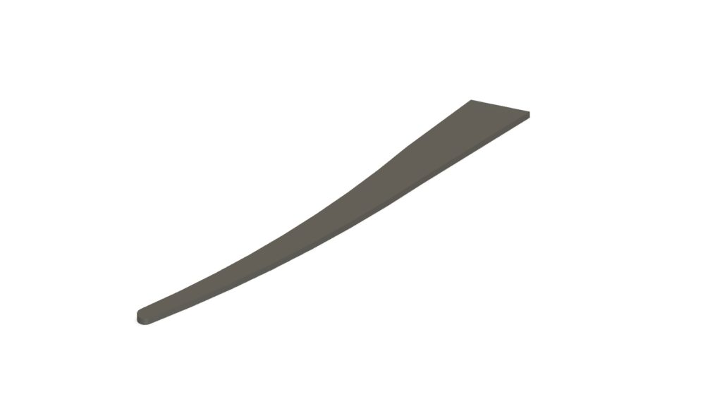
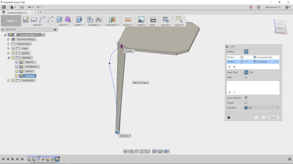
Now, we can create our loft. Choose the corner face of the table as the first profile; the foot sketch profile as the second. A weird-looking loft will be displayed since we haven’t yet applied the centerline.

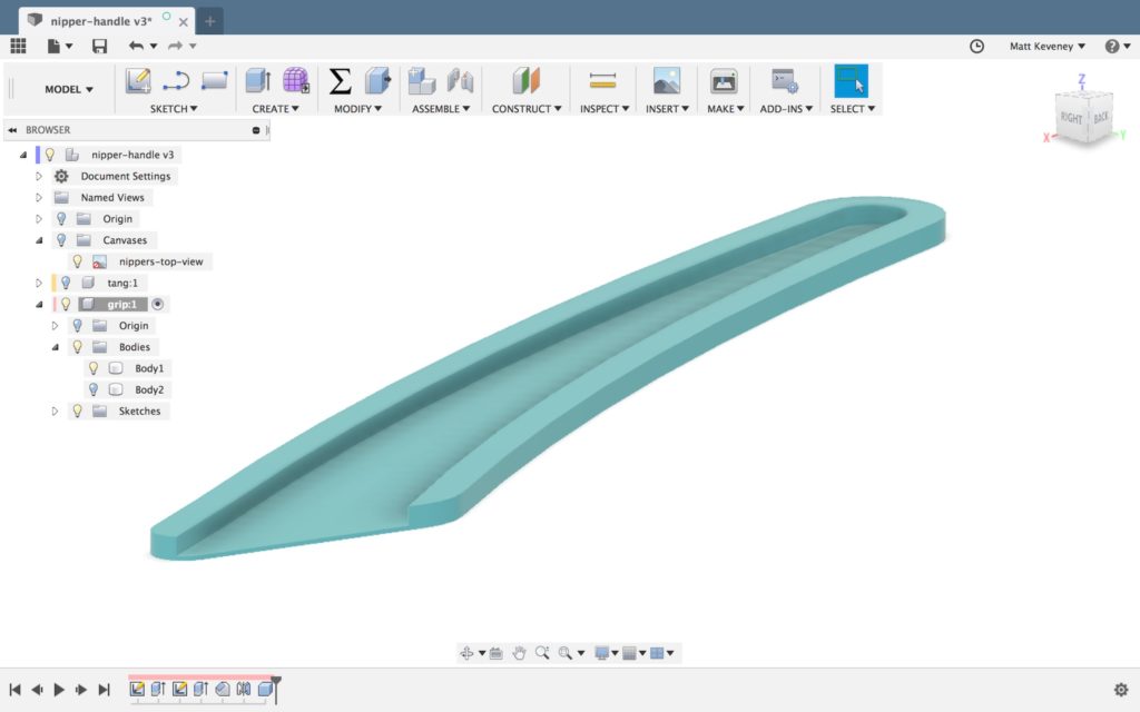
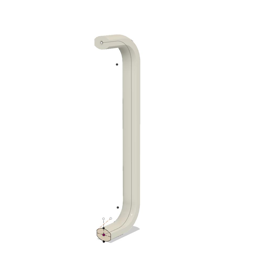
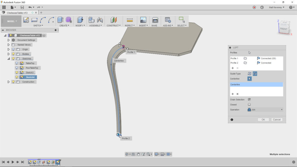
Choose the centerline guide type, and select the spline from the centerline sketch. The loft should now appear as intended.

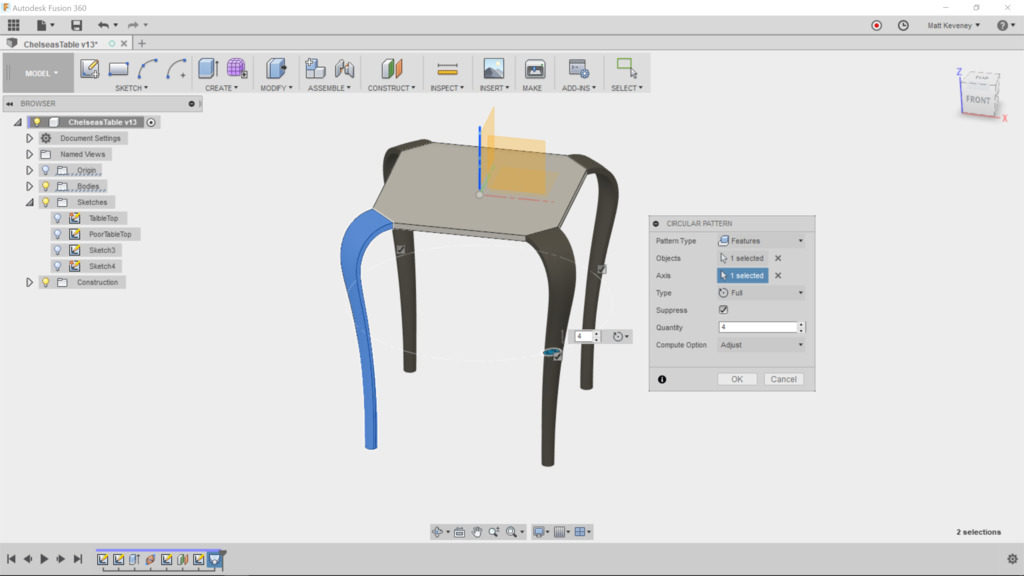
Finally, we duplicate the leg for the other three corners. Since our table is square, we could simply use the circular pattern feature. Select ‘feature’ as the pattern type and choose the loft feature from the history list at the bottom of the screen. Select the vertical axis as the axis of revolution. I told you that would come in handy! Set the count to 4, and our basic design is complete.

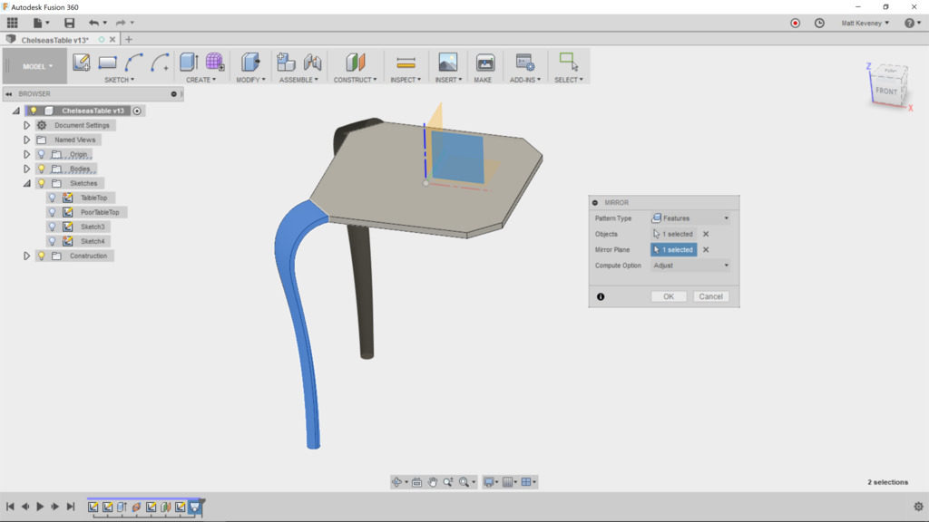
That’s fine, if we know we’re always going to want the table to be square. To make our design a more flexible, let’s use the ‘mirror’ feature instead. We’ll need to use it two times; one for each direction.

First, right click and delete the ‘circular pattern’ feature in the timeline.

Select the mirror tool; set the pattern type to ‘feature’ and choose the loft feature as before. Then choose ‘mirror plane’ and select the X/Z plane.

Now, create another mirror. Again, select feature type, but this time choose two features from the history list: the loft and the mirror we just created. Use the Y/Z plane as the mirror.

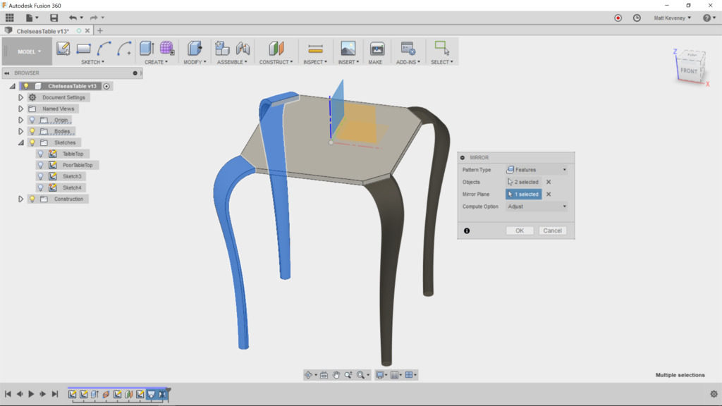
We get the same result, but we get the additional flexibility of making the table rectangular, which we’ll explore below.

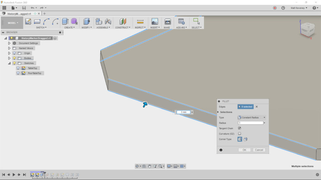
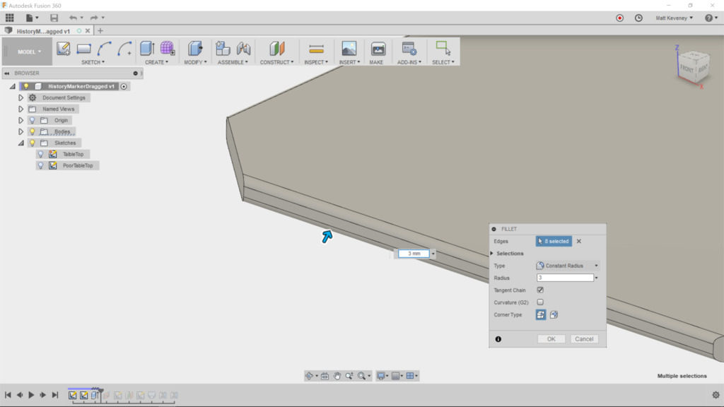
First, let’s break those sharp edges. The fillet tool is what we want, but applying it to those complex lofted edges is computationally intensive and doesn’t always produce smooth results.

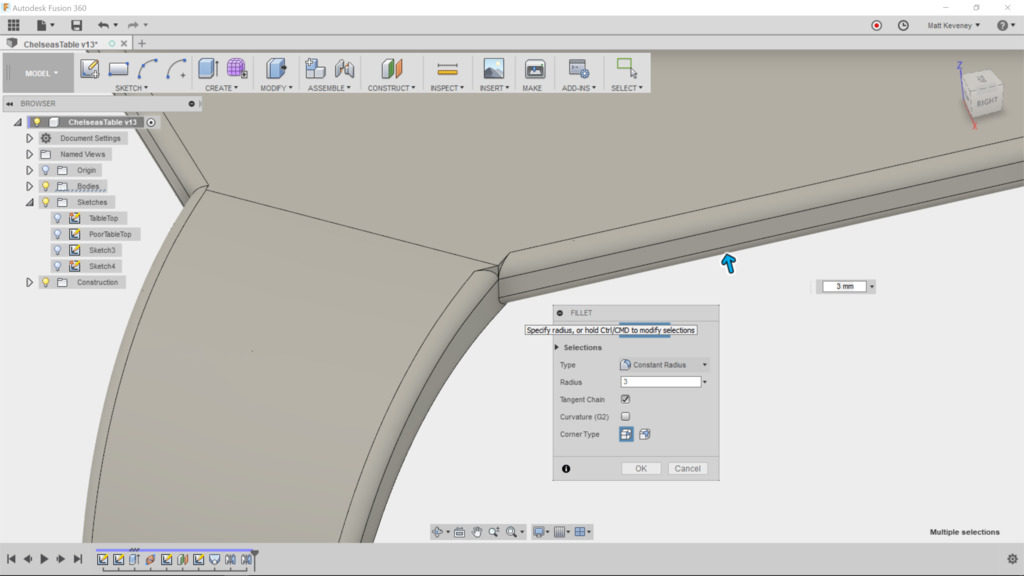
What we really wanted to do was to round over the tabletop edges before we lofted the legs. This way the loft would be created from a face that already has rounded corners. Fortunately, we can rewrite history with Fusion.

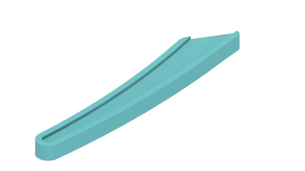
Drag the history marker to a point just past the extrude feature that created the tabletop. Now, select the fillet tool and round the edges that will end up exposed. do not round the edges at the corners, but do select both top and bottom edges, like so:


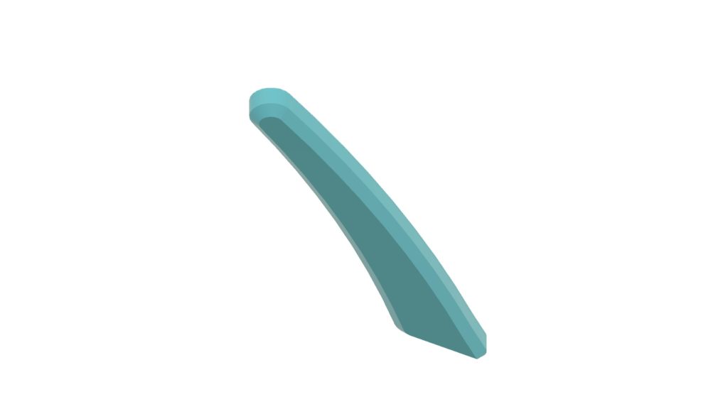
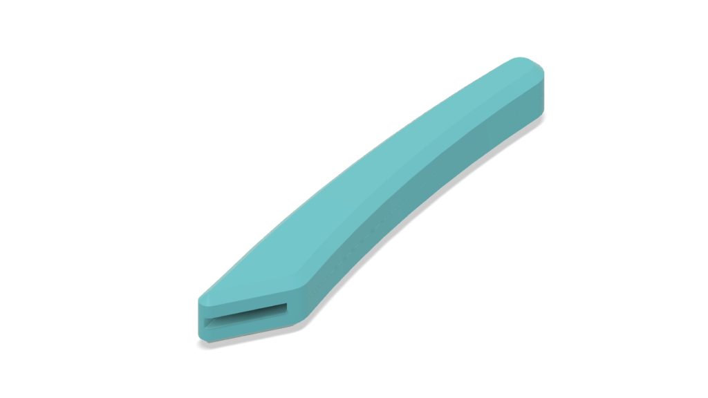
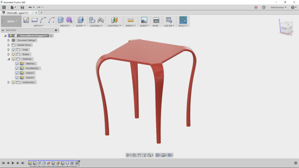
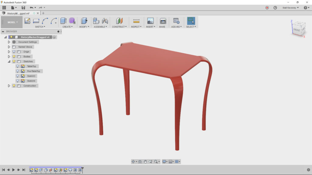
Now move the history marker back to the end. The legs now blend with the tabletop as intended. I’ve given it a glossy-plastic material.

Let’s try out a few parametric features, to see if our extra work pays off. Change the table height by adjusting that parameter we created.

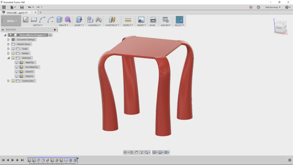
Changing the size of the feet gives the table a whole new character.

(If you expect frequent changes, it might be handy to create additional parameters for the table width, upper leg width and lower leg diameter. Then they could all be modified in a single place. I’ll let you play with that on your own.)

Change the thickness of the table by editing the first ‘extrude’ feature. It yields expected results, since we defined our table height referencing the table top, and attached the loft centerline to the midpoint of the table edge.

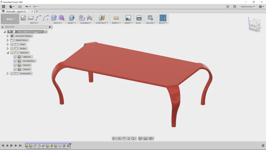
Finally, let’s make the tabletop rectangular. Edit the tabletop sketch and remove the ‘equal’ constraint currently applied to the lower and left sides. Now add a dimension defining the distance between the horizontal edges. Change the dimensions to 450 horizontal by 300 vertical.

After saving we get this:

By changing just a few parameters, we can make a wider, lower, coffee table to complement our end-table.

Thanks for reading this long-winded article all the way down to here! To get the most out of Fusion, learn to use the parametric features, and use them wisely. Neglecting them or using them inappropriately can make your designs difficult to alter later, and believe me you will always want to alter your design later. The important thing is to consider maintainability as you go along.

A 3D printed Battleship!

Over Christmas I visited my family, and got to play a game of Battleship with my niece. It was just as much fun as I remembered when I was nine!

Unfortunately, they’d lost one of the destroyers, so we had to play with just four ships.

I offered to make a replacement with my 3D printer. I took measurements on the one that remained, and modeled it in Fusion 360.

This blog post was supposed to be all about how to modify a model to avoid the use of auto-generated support material. I’d assumed that the support material would be too difficult to remove, would leave an unacceptable finish on the bottom, and that the pins would be too fragile and would break off with the rest of the support material.

Since this thing is so small, I decided to print it that way first, just to prove my point.

Unfortunately, I was able to clean it up in less than 5 minutes; the pins came out nice and strong; and the finish on the bottom is just fine. Sorry this article is so short and boring. Sometimes you just need to trust the technology and stop thinking so much!

Click here for the Fusion 360 Model file.

Happy Holidays everyone!


Fusion 360 Hangout at AMT

December 7th we started a new meet up for Fusion 360.

The group brainstormed on tool-path creation and resolved to develop an understanding of multi-stage CAM processes that can be used on the various mills, routers and cutters at AMT.

We had a terrific time at the hangout. Matt our 3D Printing steward and five others attended. All were quite experienced Fusion 360 users, in contrast to most of the previous Fusion meetings which tend to be weighted toward newcomers. I think everyone present was a AMT member.

We opted to pass the projector cord around and look at all of our projects as a group. Another approach might be to break off into twos or threes; maybe we’ll try it that way next time.

  • Bob showed us some renderings of cool guitar designs he’s been working on.
  • Rachel (aka Dr. Shiney) showed us a guitar body a client of hers needed cut; we struggled together for a while trying to figure out Fusion’s 3D tool-path generation. I think something like this would be a great thing to get Taylor’s input on: A multi-stage CAM process including facing, profiling, and 3D carving.
  • Emory gave us a quick look at his own CAM project, which involved re-mounting the workpiece to cut both sides: tricky stuff.
  • Chelsea showed us her silicone casting project. She’s come up with a pretty elaborate flask and core to be 3D printed. We’re all anxious to see the results, but those are going to be some long prints! I recommended smaller test pieces to get sizes and clearances right and generally experiment with the process before committing to the final design.
  • Matt brought along a bunch of finished projects you’ve probably seen before if you’re a regular at our Thursday meetings; nothing new, but all done in Fusion 360.