…and my thoughts on filament quality.
3D printing presents some special challenges when designing parts that must fit together. In this article I’ll explore this briefly while creating a simple plastic box with a close-fitting lid. I’ll try to make the design as flexible as possible, using Fusion 360’s parametric features.
A simple rectangular box is what I’m after. The top of the box will fit over an interior lip designed into the bottom. The side faces of the top and bottom will be flush with one another when the top is on. The vertical corners of the box will be rounded. The edges along the upper and lower face will be chamfered.
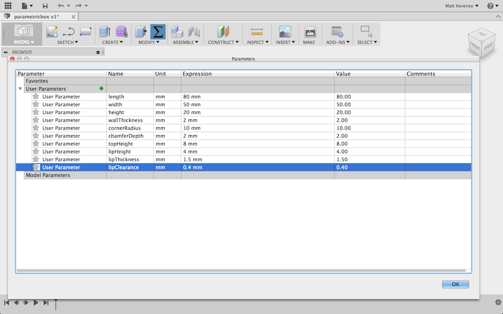
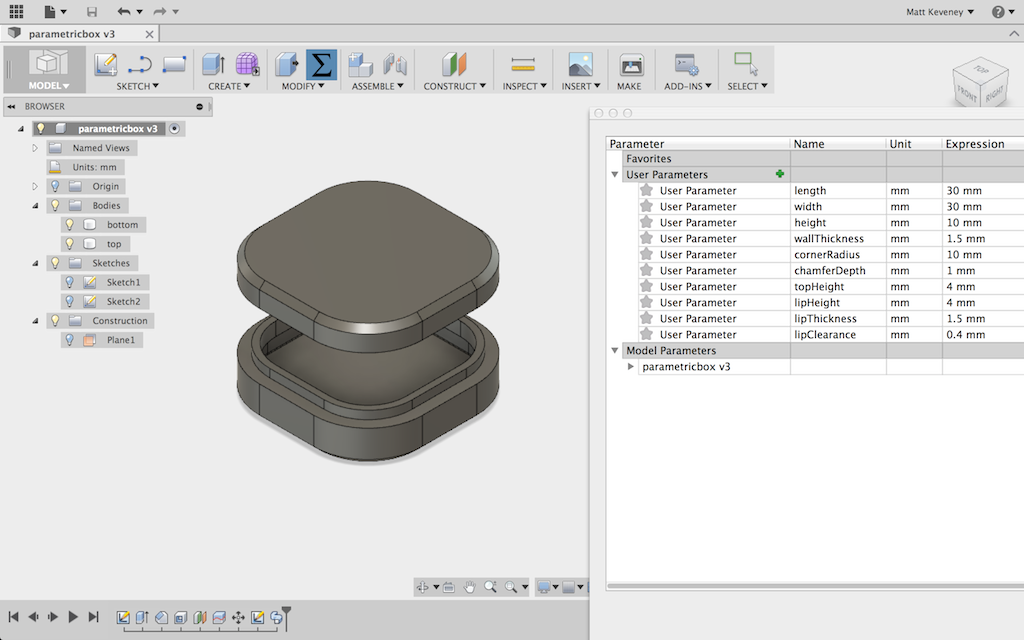
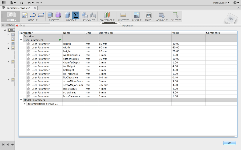
For starters, I’ll add user parameters for the features I know I want to be adjustable. I can always add more as needs arise. I’ll initialize my parameters to something that seems reasonable.
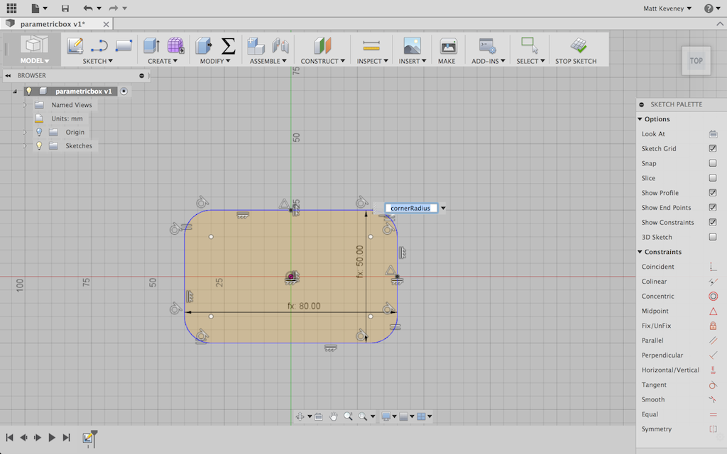
I’ll model a solid box and use the shell tool to hollow it out. Then I’ll use the split tool to cut off the top. I start with a sketch of the perimeter of the box, viewed from the top. Note that my dimensions reference the parameters I just entered. Note also that I draw the box centered around the origin. This will come in handy later.
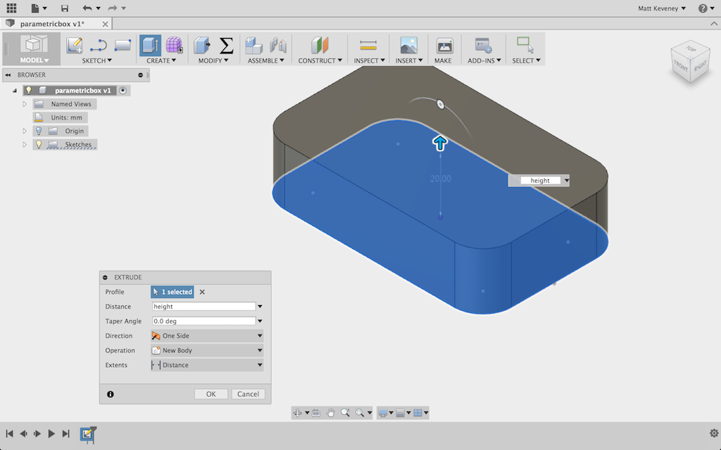
I extrude this to create the box. For the extrude height, I reference my height parameter.
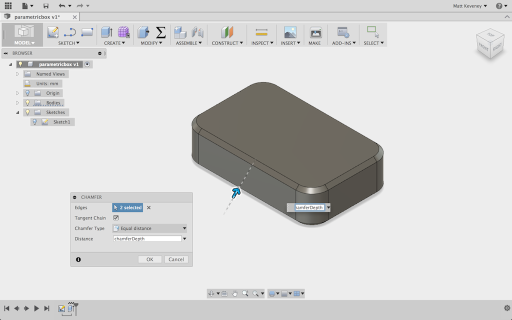
Next I chamfer the top and bottom edges. I can select all the edges and apply a single chamfer operation. It’s important to apply this before hollowing out the box, since the chamfers might excessively thin the material at the corner or even cut through.
Now I’ll hollow out the box using the _shell_ tool. Since I want an internal cavity, I select the entire body.
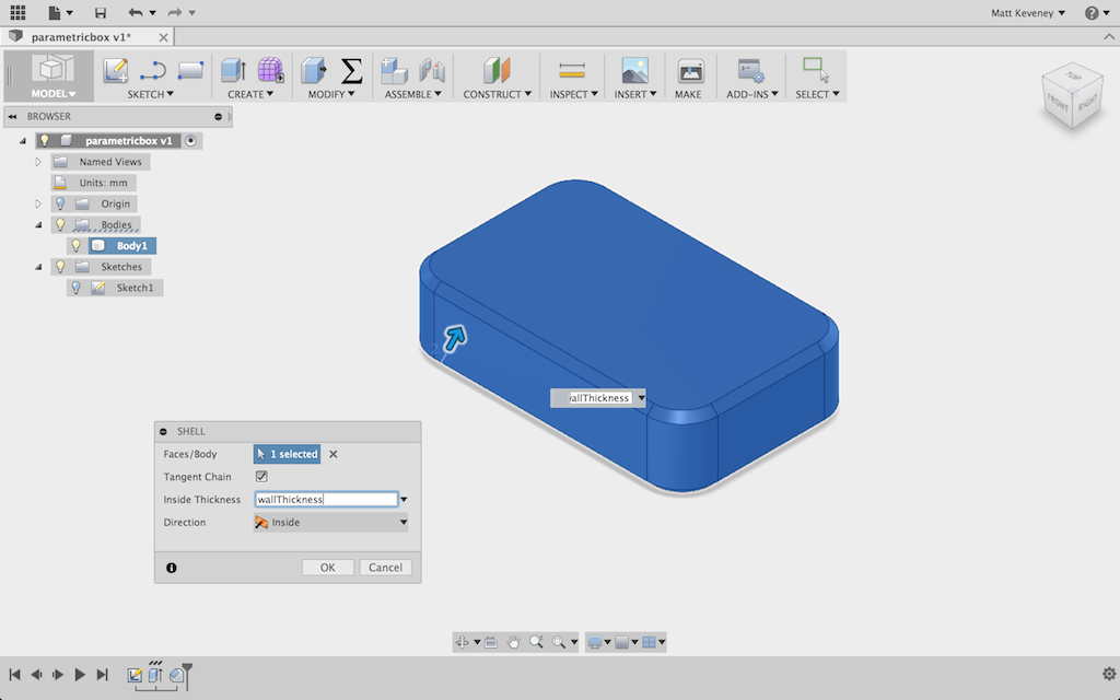
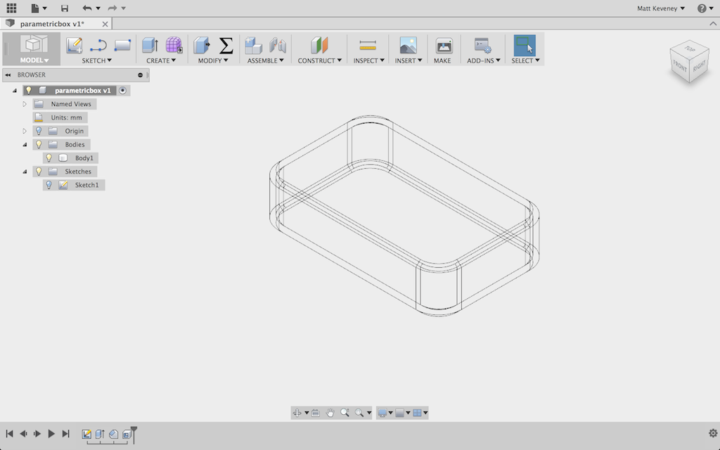
I’ll briefly switch to wireframe view to confirm that the inside has been hollowed out.
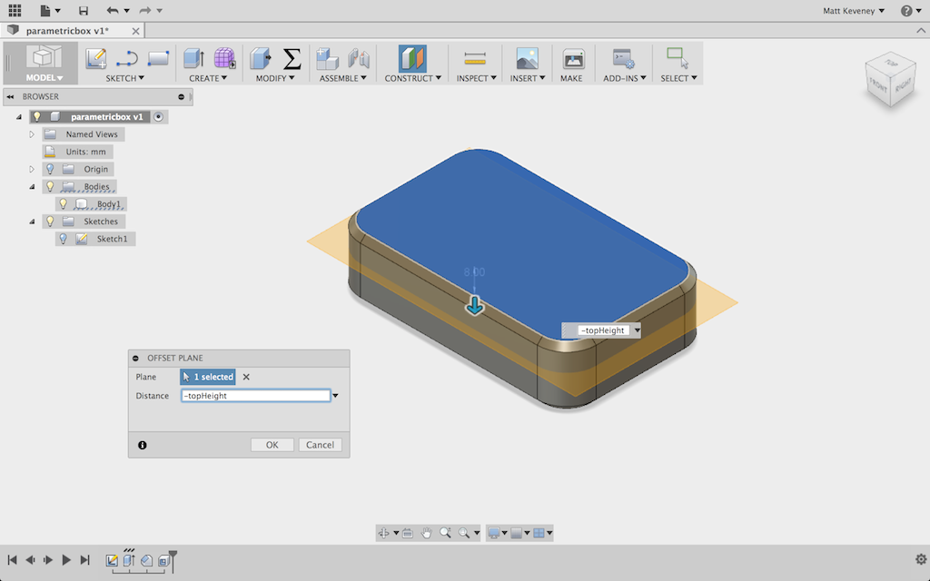
Now, I make a construction plane offset downward from the top of the box by the height of the box top.
I use the Split body tool to separate the top from the bottom.
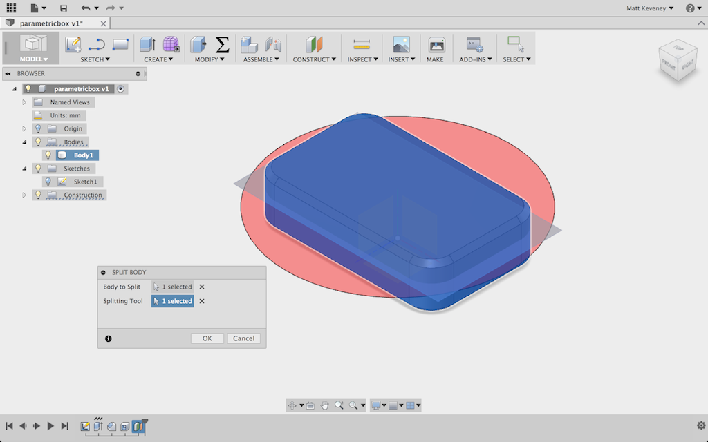
It’s a good idea to give the bodies functional names at least. If I were doing more extensive work with this box, it would make sense to put the top and bottom into separate components too, but I’ll skip that for today.
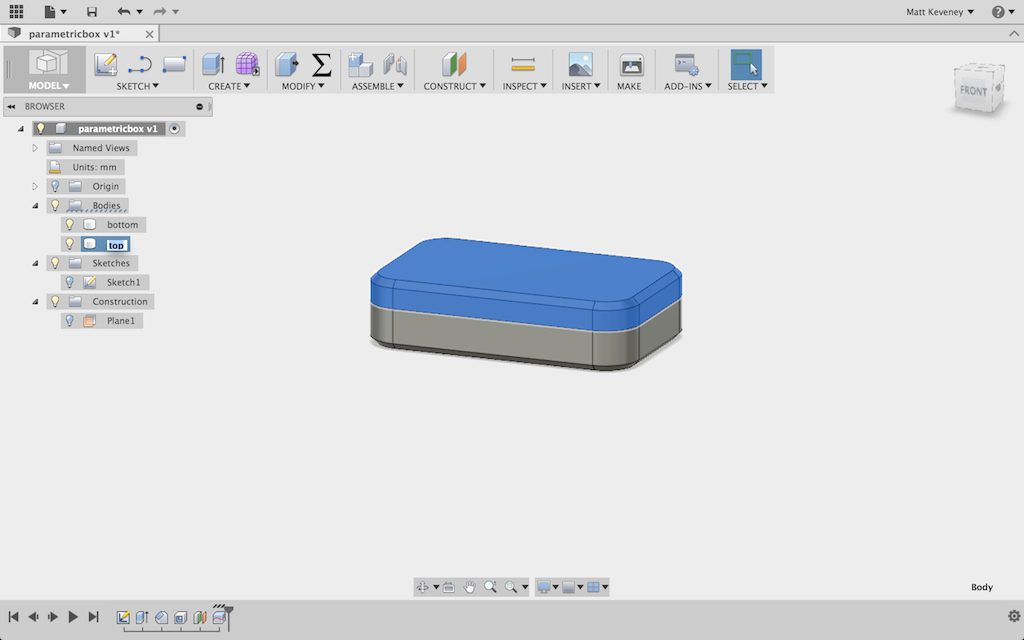
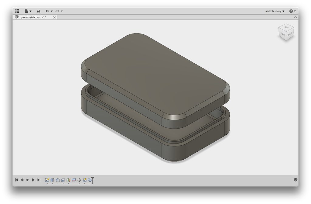
Now, just so I can see what I’m doing, I’ll move the box top up a bit. I’ll re-use the lip height for this dimension.
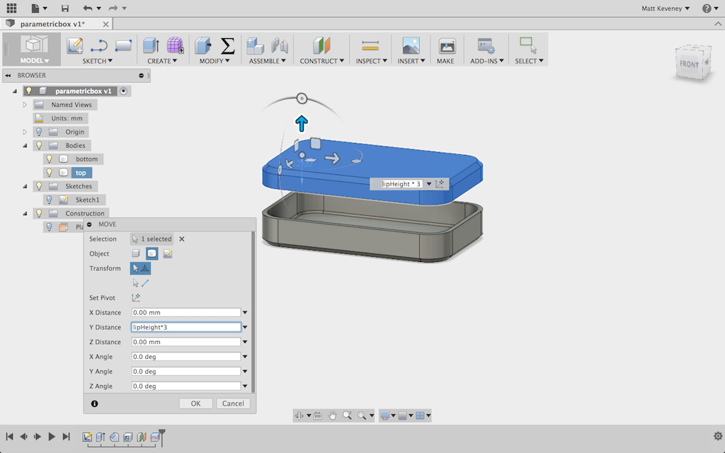
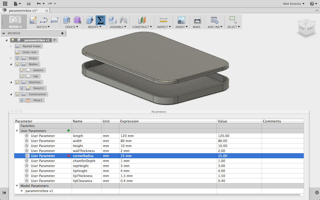
This is a good place to stop and check that the parameters actually work. I’ll make a few changes and visually check that the model seems to respect them. Here’s a wide, flat version:
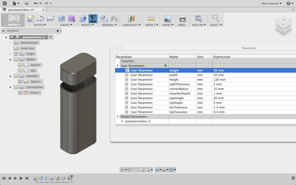
And a tall, narrow version:
Now to tackle the lip. I want the lip to project inside the box bottom and to leave a bit of clearance so that the box fits nicely. I don’t want the lip to extend all the way to the bottom of the box, so I’ll create a sloped face on its bottom edge to eliminate the sharp overhang. I hide the top first. Now, since I had the forethought to center my box, I can create my sketch on the default XY plane.
I then project the intersection of the top right inside corner and anchor the rest of the profile to it. Note particularly the small horizontal segment dimensioned to the ‘clearance’ value. I’ll adjust this parameter experimentally to get a good fit.
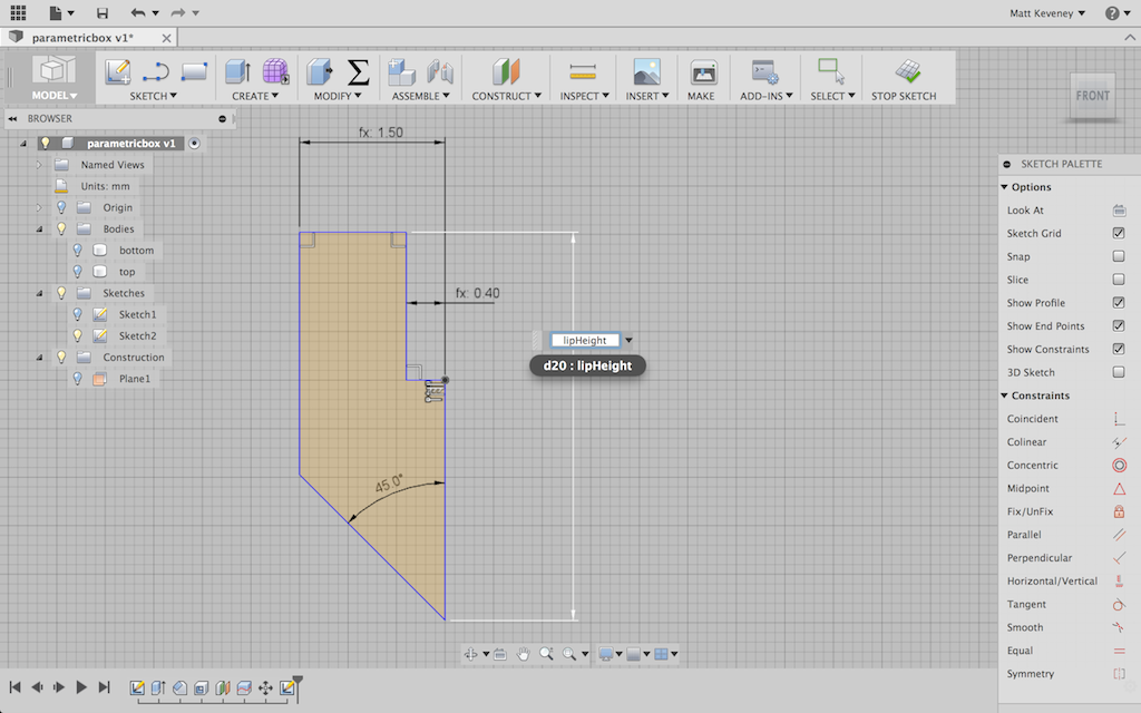
With the profile done, I use the sweep tool, specifying the top inside edge of the box as the path.
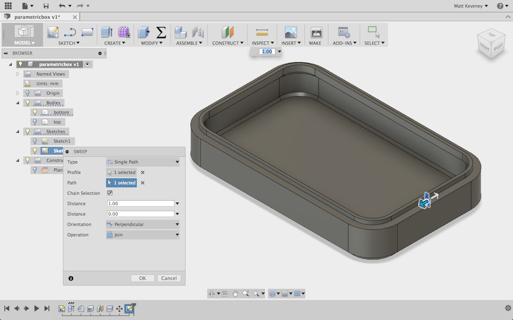
My box model is complete; now the tweaking begins. I just guessed at the initial clearance value of 0.4mm, since that size has worked reasonably well in the past. But I also know from experience that I can’t predict this perfectly. Even though the mechanism of my printer is very accurate, the final part dimensions can still vary due to slight inconsistencies in filament width, differing filament temperatures, slicer settings, etc.
Now for a bit of a diversion: Whenever I discuss dimensional tolerances, someone inevitably asks whether “high quality” (read: expensive) filament will solve the problem. Certainly the premium filament vendors would like you to think so, but it isn’t true in my experience. No matter how much I spend, I see variations in filament diameter and melting temperature that are significant enough to cause slight variations in part dimensions.
I now use inexpensive filament mostly from vendors on eBay. I choose vendors with a reasonable level of positive feedback, and have had very good luck lately (14 spools purchased over the last 8 months or so; all work well; most under $19.00/kilo including shipping). When I did choose a more expensive vendor (still just $22.00/kilo), it was only because the cheaper places didn’t have the colors I wanted!
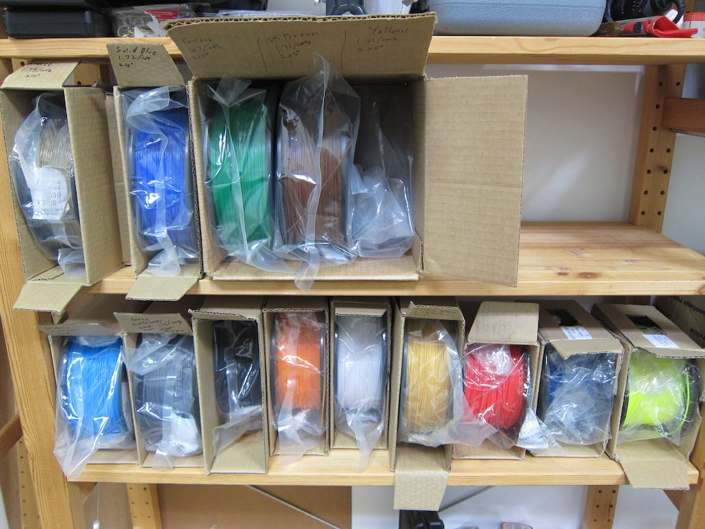
I think that filament quality in general has improved in recent years. Here’s a fairly current review of some cheap filament from Hobbyking that seems to agree (Hobbyking is currently selling $10.00 spools that have just 1/2 kilo, so be sure to compare fairly). I think the situation was worse a few years back, so check the dates on what you read.
I also think that some of the complaints may be from folks venting their frustration instead of acknowledging the simple fact that all manufacturing technologies are imperfect.
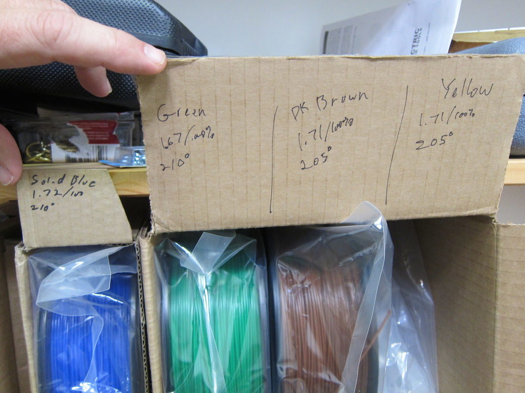
Instead, we can learn to work within the limits of the technology, including variations in filament properties. To help with consistency, I always measure my filament diameter and record it along with the temperature and any other non-default slicer settings.
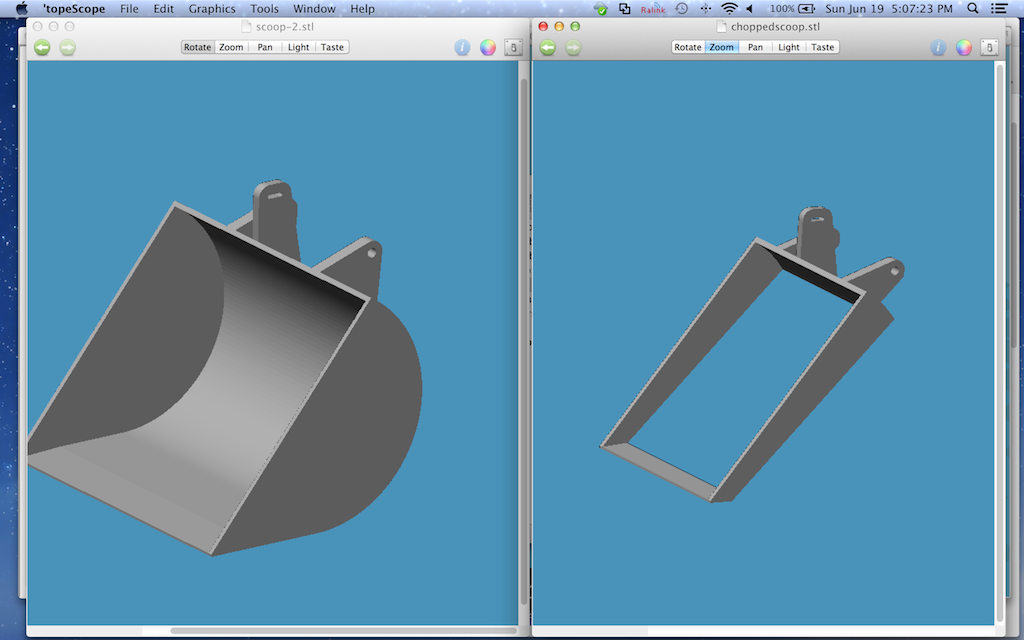
Even with all that preparation, a really close fit always seems to require some experimentation. Rather than fight it, I design my parts to accommodate these experiments with a minimum waste of time and material. Sometimes I make an abbreviated copy of the part so I can test the fit without printing the entire thing out. The following screenshot is the model I used to print the scoop for our dart-scooping-robot at MakerFaire. The model on the right is the abbreviated version I tested before committing to the five-hour print on the left.
Of course, the best strategy might be to design your work in such a way that a close fit is not necessary at all! More on that later. For now I’ll proceed with the experimental technique.
Since I’ve made this box parametric, I can simply enter parameters for a smaller box! Once I figure out the proper clearance value for my filament and slicer settings, it ought to remain valid for any size box.
So, let’s start with a very small box: 30x30x10, using my initial guess for clearance of 0.4mm.
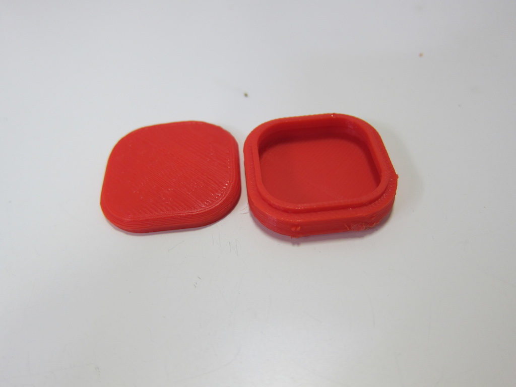
Well, that gave me reasonably good results on the very first try. The top fits, but might actually be a wee bit too tight. I’ll try again, increasing clearance to 0.5. I’ll also see if I can go with a wall and lip thickness of just 1mm, and I think I had the temperature a bit too high, so I’ll adjust that too. A more scientific approach would be to modify just one variable at a time, but I think I can get away with breaking that rule here.
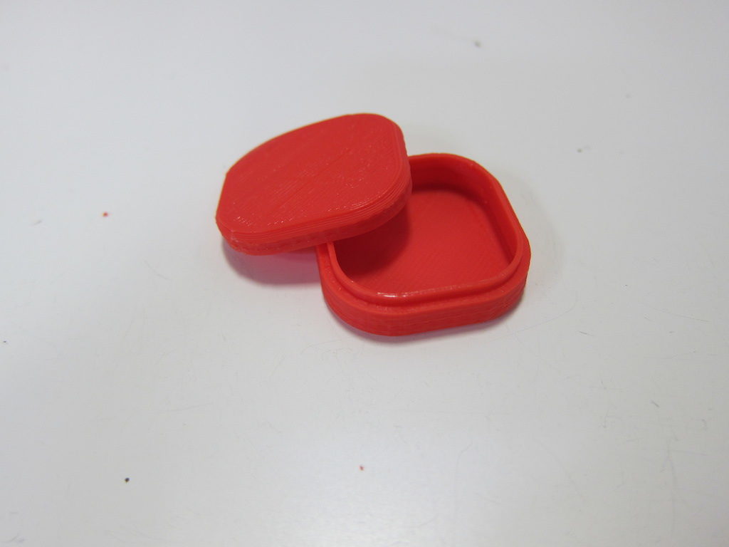
Looks good; the new wall thickness is fine. The lid fits with a bit of wiggle room and no longer snaps in place. For a good friction fit, I think something closer to 0.4 than 0.5 would be about right for the clearance parameter. I’m confident enough at this point to try something bigger: 80x60x25.
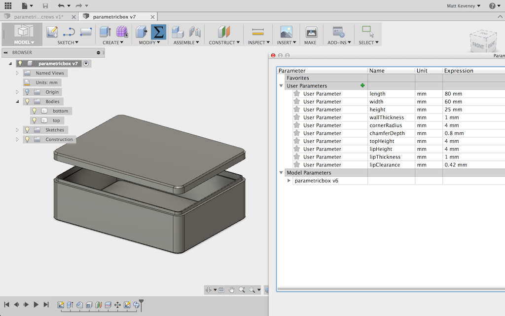
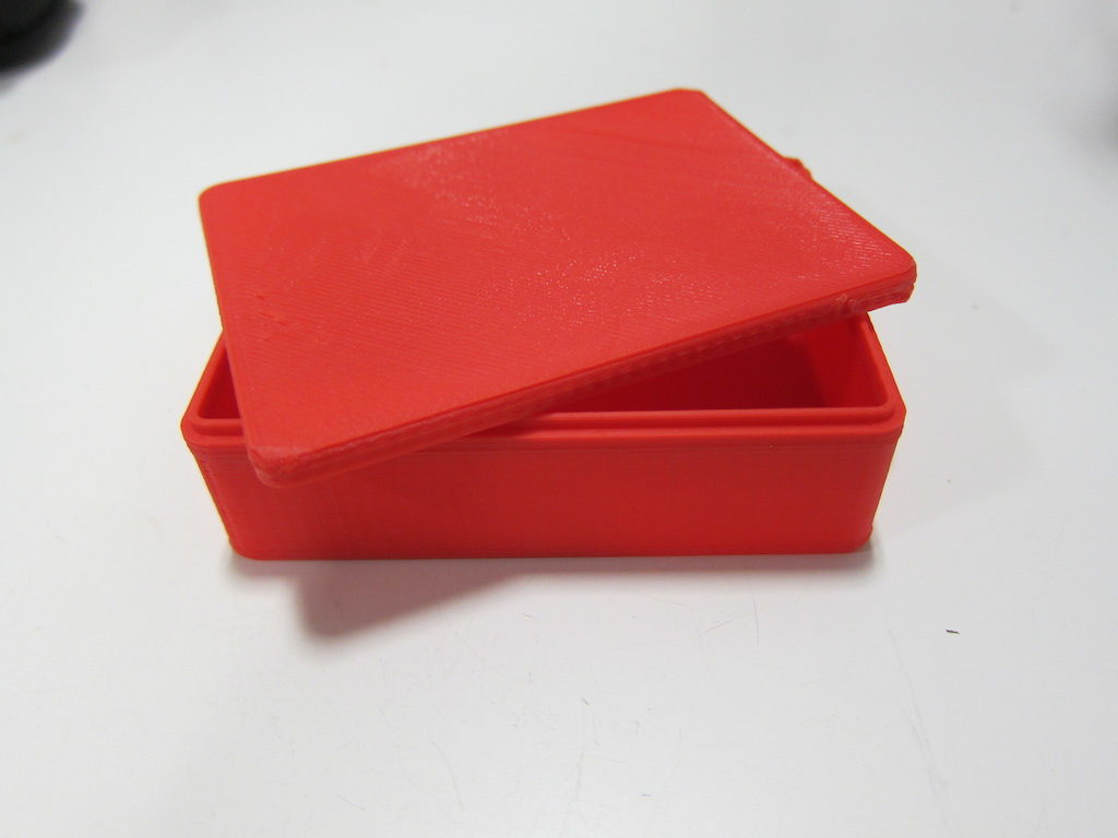
And it works great.
Instead of doing all that work to get a close interference fit, I can just use screws to fasten the box together. I could eliminate the lip altogether and rely on the screws to align the top and bottom, but I’ll keep the lip, modifying the profile so that the mating face slopes slightly inward. Now, the lip serves merely to align the top as it is fastened in place.
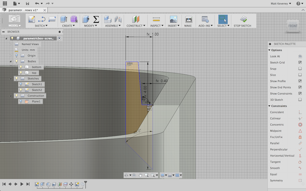
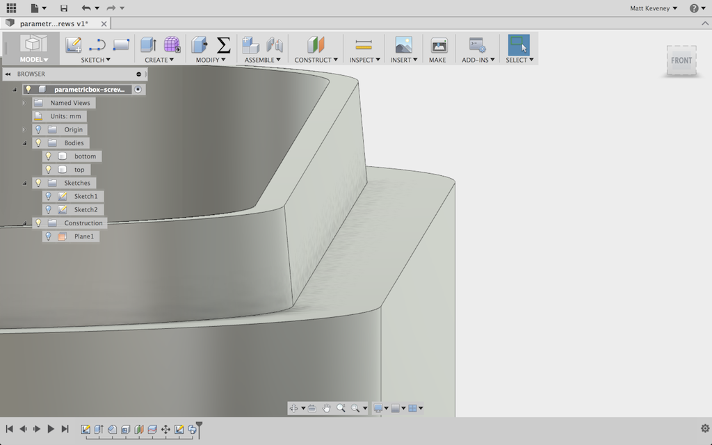
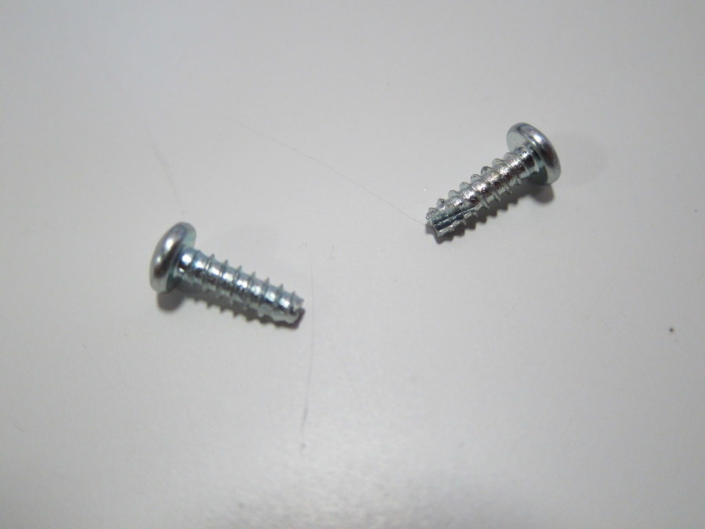
I’ll design for two of these these self-tapping screws in opposite corners of the box. They require a smaller hole in the bottom, where the threads bite in, and a larger hole in the top. If you get the hole sizes right, you can even get away with normal (not self tapping) machine screws.
The screws are not long enough to reach to the bottom of the box, so I’ll add a boss for the screw to bite into. Since this boss is so close to the edge of the box, I’ll extend material to the sides of the box in the lower portion. Here are the parameters I’ve set up:
It might be tempting to center the screw right at the center of the curved corner profile, but remember that this is a parametric feature. If the curve radius is made very small, the center would not be an appropriate place for the screw. Instead, I’ll make an independent parameter to fix the screw location relative to the inside edges of the box. This way, I’ll have the option to align the screw with the corner if I like.
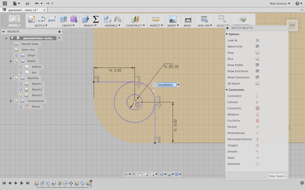
I’ll extrude the boss itself almost to the inside top of the box. I used a formula that didn’t show clearly in the screenshot: height – 2 * wallThickness – bossClearance.
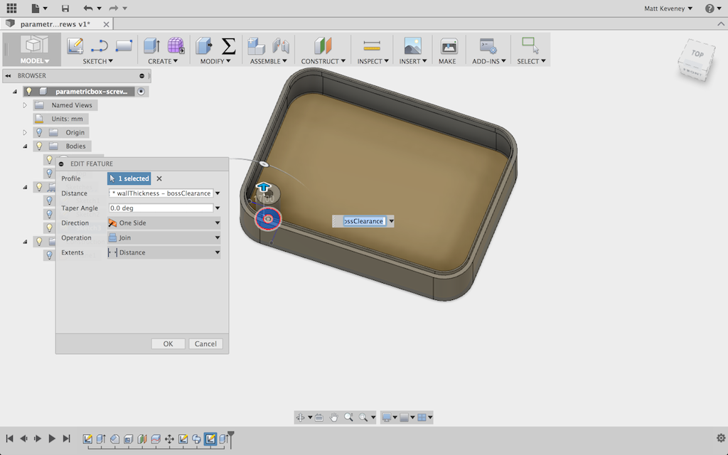
The reinforcement is carried up to the middle of the lip.
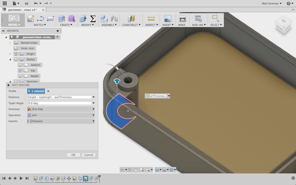
Then I use the circular pattern tool to copy the boss and reinforcement to the opposite corner. Another good reason to center my part around the origin.
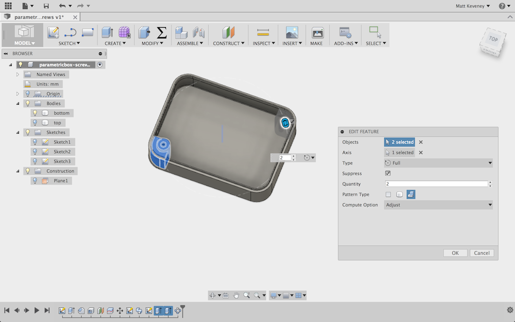
I adjusted the boss-related parameters a bit just to assure myself that they’re working properly. So far so good.
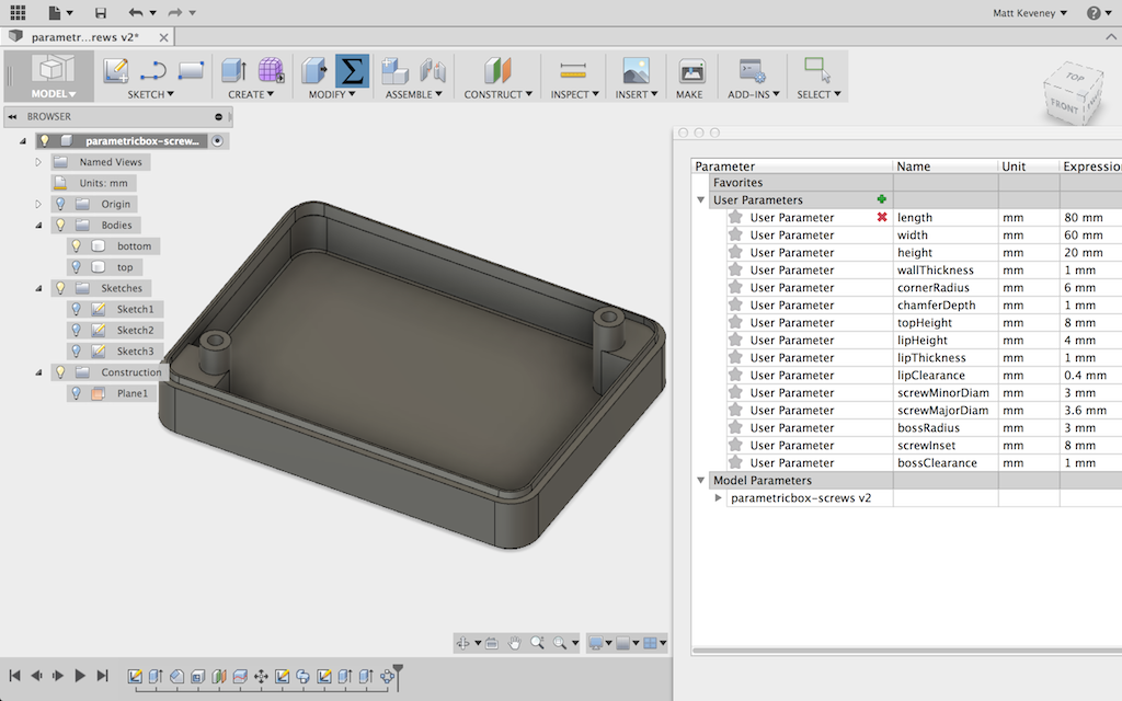
Now, I unhide the top, create a sketch on it, and project the boss perimeters onto the sketch. Note that I’ve projected the outer boss perimeters; not the central holes. This avoids confusion with the clearance holes in the top which have a slightly larger diameter.
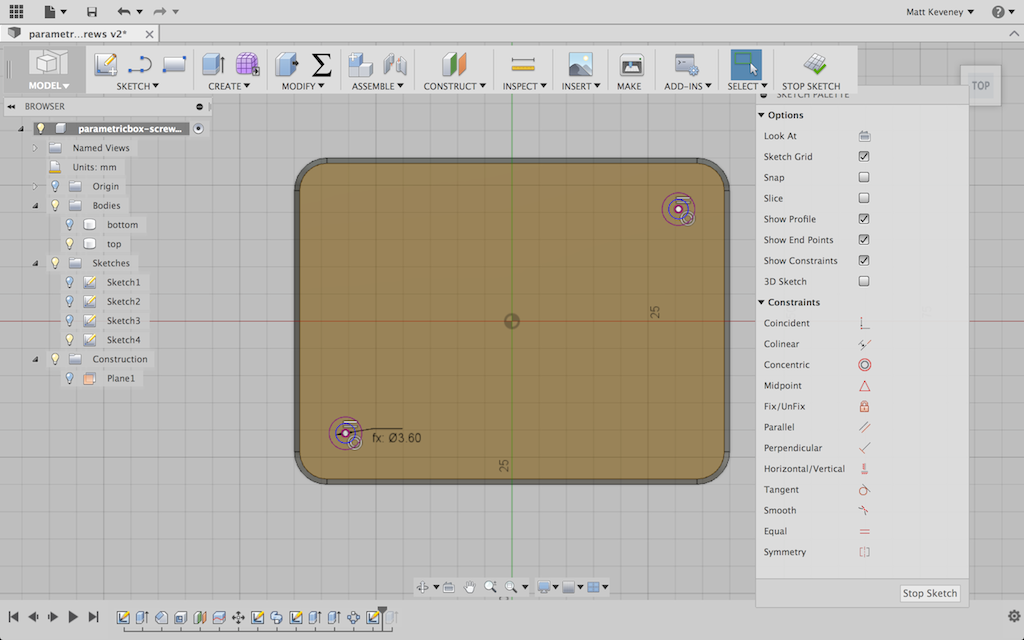
And, finally I use the press pull tool to bore the holes. I hide the bottom first, so I don’t accidentally bore the hole through both parts.
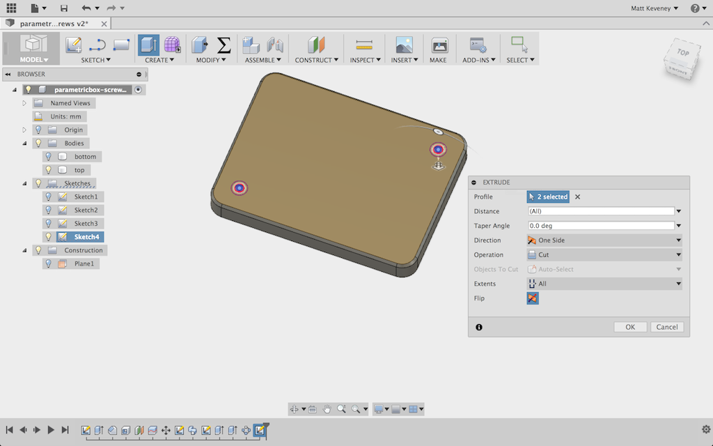
A few parameter tweaks later, I’m ready to print!
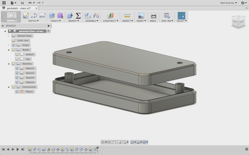
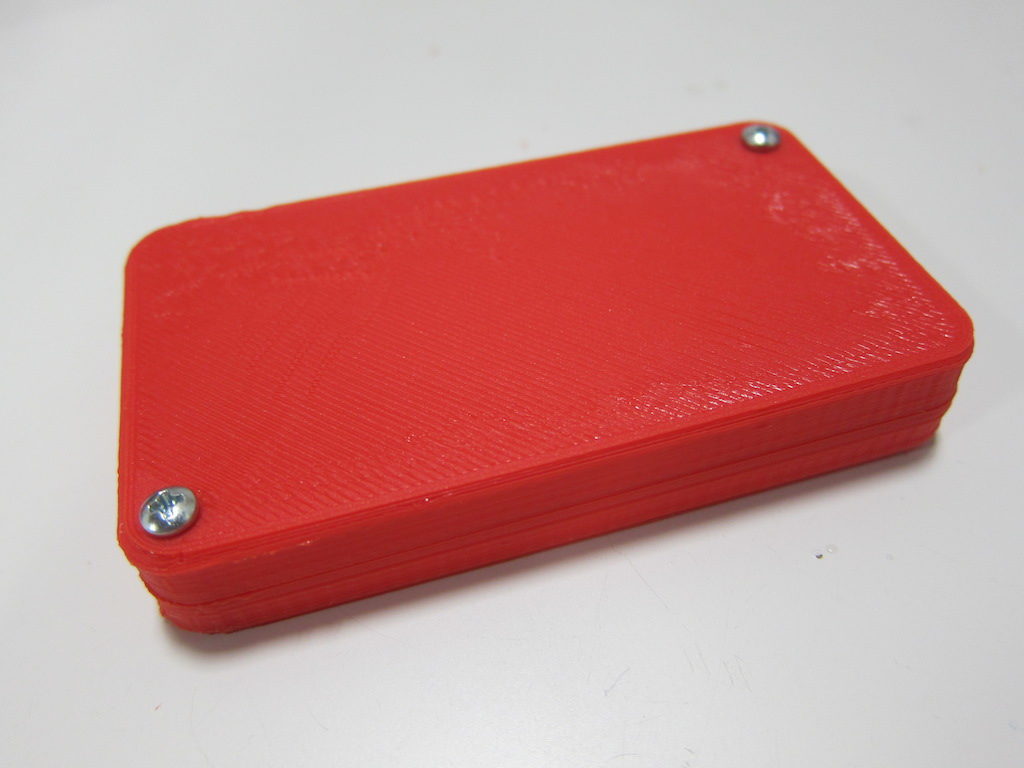
And this is the result. You may download these models below. I’ve tried to make them as flexible as possible; I hope you find them useful!
Click here to download the Fusion360 model files.
Update:
Shortly after publication, I found a bug in this model. See my follow-up article:

